

 If you’re involved in the management, operation, maintenance, and/or overhaul of one or more LM2500, LM5000, LM6000, or LMS100 engines and haven’t participated in an annual meeting of the Western Turbine Users Inc, ask yourself this question: Why did about 400 users from 20 countries and 41 states attend the organization’s 27th Annual Conference & Exhibition at the South Point Hotel & Spa in Las Vegas, Mar 19 – 22, 2017?
Answer, if you can’t guess: It’s the largest, most comprehensive technical meeting in the world for these engines. You can help but learn from colleagues in the breakout sessions for each machine, from top engineers at GE and the OEM’s Authorized Service Providers (ASPs), and from representatives of more than 150 suppliers of products and services for these specific gas turbines. Note that the ASPs were known previously as “depots.”
If you’re scratching your head thinking “well, I just attended a year or two ago and I’m up to date,” scratch some more. To keep your plant competitive in today’s challenging world of must-take renewables, of serious financial penalties for not satisfying grid contractual requirements, and of mandated shutdowns for relatively minor emissions excursions, your mind must be as finely tuned as the equipment in your charge.
Register November 1 for the next meeting in Palm Springs, Calif, March 18 -21, 2018 (box).
This is the second CCJ report on WTUI’s 2017 meeting; the first appeared last issue. Here the editors offer an overview of the opening presentations by the ASPs and then walk you through some of the details shared during the LM6000 and LMS100 Breakout Sessions. Acronyms are used frequently in those sections; if you’re not familiar with them, refer to Sidebar 1. The report concludes with a review of the vendor fair.
TICA presents awards for excellence at Western Turbine
 The Turbine Inlet Cooling Assn (TICA) recognized Riverside Public Utilities and Princeton University at the 27th annual meeting of the Western Turbine Users Inc with its 2017 Excellence Award for successful implementation of turbine inlet cooling on GE aero gas turbines.
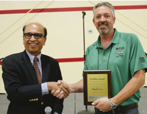
Riverside received the award for its 3500-ton centrifugal chiller system, which cools inlet air to the four LM6000PC engines at the Riverside Energy Resource Center from 110F to 48F. TICA Executive Director Don Punwani (at left in photo) said the TIC system, supplied by TAS Energy, enables the plant to produce an additional 66 MW in hot weather. He presented the plaque to the utility’s Generation Manager Chuck Casey.
The Energy Plant at Princeton was recognized for implementing a chiller-based TIC with thermal energy storage to serve its LM1600 engine 42F air on a 98F day. TICA members CB&I and The Cool Solutions Company were major participants in the project.
ASP profiles
ANZ Gas Turbines. The joint venture between Air New Zealand and Consolidated Asset Management Services, Houston, created a world-class field service organization for North America, based in Bakersfield, Calif. Frank Oldread is GM of the company, Jimmie Wooten is manager of turbine maintenance, and Bob Cox heads up marketing and sales. All are well known in the aero community; in fact, Oldread and Wooten were WTUI board members when users.
The company supports LM2500, LM5000, and LM6000 gas turbines. Plus, ANZGT is responsible for managing the aftermarket needs of the LM5000 fleet, which numbered more than 100 engines 10 years ago and only three dozen today.
To provide timely, quality service, the Bakersfield group is reaching out to owner/operators to develop a clear strategy for each power producer in the near term. It’s no longer possible to run a traditional field/services/spare parts strategy given the wind down of the fleet. Several owners are not planning any maintenance/overhaul before decommissioning their engines.
IHI GM Takashi Yamamoto reviewed the company’s deep connection with the LM6000: parts manufacturing (CRF), package and control-system design (for the PC, PD, PF, PG, PH, and PF+ engines supplied by GE), BOP design, EPC contracting, and maintenance (in the field and in the shop).
The company’s aftermarket network includes two Level 4 shops—Kure Works (Hiroshima) and Mizuho Works (Tokyo)—plus service centers in Thailand, Australia, and Cheyenne, Wyo. Yamamoto stressed the Level 2 Cheyenne shop’s ability to respond quickly and effectively to unscheduled events. Its assets include rotable exchange components, shipping containers, critical parts, and lease engine.
The GM next introduced attendees to the company’s other business units in the US, including the following:
- Overland Park, Kans. HRSGs, SCRs, duct burners, and related equipment.
- Chicago. Energy storage (batteries), control software.
- Aliso Viejo, Calif. Aero GT operations, O&M contracts.
- Houston. LNG, oil and gas plants.
MTU Maintenance focused on its facilities—a Level 4 service center in Germany and five Level 2 service centers worldwide, including one in Dallas. The company’s experience is vast—hundreds of LM engines have been repaired in the German shop, thousands when you add in the CF6 because of the company’s large aircraft business.
The modern test facility in Berlin-Brandenburg with Mark VIe controls operates under real-load conditions using a generator. The facility can handle all types of LM engines, including the 2500+G4 and the 6000PF.
TransCanada Turbines (TCT). Dale Goehring and Darcy Simonelli handled the presentation duties. The company has an aggressive health and safety (HSE) program. It’s the first subject TCT discusses each year at WTUI. Goehring seemed almost apologetic in Las Vegas because two HSE “events” were recorded in 2016 for more than 475,000 man-hours worked. Perhaps that was because there were no “events” recorded in 2015 when more than 480,000 m-h were worked.
Goehring spoke briefly about the numbers of training hours, management visits to work areas, and inspections it takes to achieve such an enviable record—huge. Commitment squared. Training alone last year totaled some 3500 hours (round number). Still, 241 safety observation cards were issued to identify concerns, need to stop work, potential for an incident, unsafe acts/condition, and quick fixes. More than half of those cards were issued at customer sites. All SOCs are tracked and trended; both positive and negative observations are recorded.
The focus on people continued. The steady and experienced workforce averages 20 years in the industry, 10 at TCT, and has a turnover of less than 3%, Goehring said. The field-service team numbers more than 50 to serve 124 customer sites in 34 countries, each member averaging more than 50 hours of training annually.
LM6000
The LM6000 is the most popular of Western Turbine’s four breakout sessions, attracting more participants (300 plus at the 2017 meeting in Las Vegas) than the LM2500, LM5000, and LMS100 breakouts combined. Andrew Gundershaug, plant manager of Calpine Corp’s Northern California Peakers, chairs this group.
Gundershaug’s day job is to manage seven LM6000 peakers at different sites, so there isn’t much in the way of “issues” with these engines that he hasn’t experienced firsthand. That, plus two decades of work on LM engines, exposure to problems faced by others as a WTUI conference attendee since 2001, and excellent speaking and audience-engagement skills, place Gundershaug among the most capable of user-group floor leaders.
The primary responsibility of breakout chairs at WTUI is program development. While that’s true for steering committee members of other user groups as well, at Western Turbine this is pretty much a second full-time job; the work is year-round, with no financial remuneration of course.
Gundershaug works collaboratively with subject matter experts at the Authorized Service Providers and the OEM, as well as Western Turbine colleagues, to develop the annual “LM6000 O&M Bible” presented to each participant in the breakout session to facilitate learning and note-taking. This year’s 200-page full-color book had three major sections:
- ASP findings in the shop, and in the field, the previous year.
- Details on the OEM’s efforts to resolve fleet issues, plus mods and upgrades available to owner/operators to improve performance, safety, etc.
- Notes on topics for the package discussion integrated into the busy agenda.
The first three hours of the breakout was devoted to presentations by ASP representatives who compiled the drawings, photos, and notes on significant issues identified in 2016—vital for users looking ahead to the next overhaul and all those responsible for engine operations. The presenters:
- Ken Ueda of IHI Corp, 17 years of experience on LM6000 engines—including roles in R&D, maintenance engineering, customer support.
- Ralph Reichert of MTU Maintenance, 21 years of GT experience—including aircraft mechanic, field service engineer, maintenance shop engineer.
- Steve Willard of TCT, 15 years of LM engine experience, with involvement in component repairs, test-cell operations, project management, and engineering.
In all probability, nowhere except Western Turbine would you find such a capable “faculty” for sharing their knowledge on one of the world’s most popular gas turbines for electric generation. Today, the fleet totals 1250 engines in round numbers—one-third of them equipped with DLE combustion systems.
As you read on, important to keep in mind that the editorial goal was to profile some of the session’s highlights, not to compile a comprehensive summary of the proceedings. You can get that via the Western Turbine website, where all the ASP and OEM presentations are posted along with a 35-page chronology of the LM6000 sessions, compiled by Steven Giaquinto of Strategic Power Systems Inc. SPS engineers help support the WTUI mission by taking notes for the membership during the breakout sessions. Note: Conference materials are available only to registered WTUI user members. Not a member of Western Turbine Users Inc? Sign up today at www.wtui.com.
After opening remarks by Chairman Gunderson, including the all-important safety message on how to evacuate in the unlikely event of an emergency, TCT’s Willard got the session rolling. He reminded attendees of the value proposition associated with the three Level 4 ASPs serving the LM6000 community:
- Access to GE technical documentation.
- Access to GE parts and service support as defined in the license agreement.
- Approved vendor list for component repairs.
- Departure records from GE to cover minor deviations to O&M and repair procedures.
|
Sidebar 1: Acronyms to remember AGB—Accessory gearbox |
Mention of the service bulletins (total of 17) and service letters (five) released since just before the 2016 meeting was made next. Willard noted that it was a busier year than usual concerning document release.
He then passed the mic to IHI’s Ueda, who presented on CRF vent duct improvement, engine monitoring, IGB housing deformation, and a No 4B bearing event. See Sidebar 1, “Acronyms to remember” if you’re unfamiliar with the shorthand.
The CRF vent duct has experienced cracking (attributed to high levels of stress) at the fillet weld that joins the wear sleeve to the duct body. Oil leakage is a possibility. A smoky condition in the package would suggest that. Service bulletin (SB) LM6000-IND-320, “Improved CRF vent duct,” eliminates the fillet-weld wear sleeve and identifies a material change from Type 321 stainless steel to Inconel 625 (to increase the strength margin).
An increasing T3 (HPC discharge temperature) difference among the four sensors provided (A/B/C/D) was detected; the T3-D signal was abnormal. Inspection of cable, connectors, and T3 sensors were recommended by Ueda. A user mentioned that one of his engines exhibited discrepancies in T3 signals but they couldn’t identify the cause.
Another attendee reported seeing black marks in connectors that were removed by cleaning but reappeared a few months later. That led to the question, “Is there another cable design to improve this? We are getting oxidation in there.” An OEM representative said he was not fully aware of repeated issues on connectors and asked that users provide more information on these occurrences.
Cabling can be problematic. Yet another user said engine oscillations can cause connectors to wiggle loose, sometimes resulting in an engine trip. A colleague said a robust maintenance program was required to mitigate cable issues. At his plant cleaning and tightening is done twice annually.
No. 4B bearing failure. A B-sump alarm alerted to high scavenge oil temperature and high deltaP across the scavenge oil filter. Metal particles were found in the sump. Engine sleuths went to work, identifying deep flaking on the outer race of the No. 4B bearing at the 6 and 12 o’clock positions. They said such deep flaking at these positions indicated damage was done while the engine was not running. The root cause: An air-ride truck was not used for ground transportation and the damage occurred from excessive and repeated vertical shocking.
MTU’s Reichert was next to the podium. He addressed the following:
- CRF oil leak, SB 307/308.
- TRF D/E sump, SB 323.
- SB 322 HPT second-stage nozzle retainer update.
- High C-sump oil temperature/pressure.
- DLE combustor improvement.
- LPT second-stage blade shroud deformation.
- Peak versus baseload component degradation considerations.
Again, if any of these speaking points of interest to you are not summarized below, consult the presentation materials available on www.wtui.com. Access is denied to all but user members of the organization.
CRF oil leaks got considerable attention from the group. Here’s the background: Service Bulletins 233 and 236, issued September 2008, superseded SB 154 with the objective of mitigating the risk of oil leakage in the sump area. Shortly thereafter, some engines were found to have deformed J-tabs; three had oil leaks in the C sump area. J-tab distortion was attributed to an interaction between thermal expansion in the sump area and oil-tube (manifold) vibration.
In January 2015, SB 307 (SAC)/308 (DLE) replaced 233 and 236, specifying the following: removal of the heat shield, a wider wear sleeve, and a wider P-clamp for the affected oil manifold. SBs 154, 233, and 236 were canceled.
However, while the recommended fixes in SB 307/308 stopped the leaks, they were not without issues. Bent J-clamps were found after about 300 to 500 hours of operating time on a couple of engines. The good news is that the OEM does not view distorted clamps alone are a reason to pull the engine. Periodic monitoring of the J-clamps is recommended.
Significant discussion ensued. A user asked, “Can you fix clamps in the field?” An ASP representative replied, “This is a Level 4 service bulletin and not recommended for the field.” A follow-on comment made by someone else at the front of the room, “The clamps move and then fretting occurs and tubes leak; then the engine smokes. Important to recognize, an ASP rep said, is that you can monitor the clamps with a borescope. If a clamp bends, he continued, don’t worry; sometimes clamps stop bending. The important thing is look for oil, which will tell you when to think about repairs.
Yet another question: “Which is worse, a twisted clamp or a broken one?” ASP response: “With a twisted clamp, the support is still there. However, there have been some cases where the clamp was removed and the engine came back to the shop with no adverse effect.”
Peak versus baseload operation. An important presentation; it was made last year as well. Photos of damage attributed to “hard” operation are available online and offer valuable lessons for the O&M staff. The takeaway for owners of peakers is that they will cost you more to operate because hardware takes more of a toll than it does on baseload units. The LM6000 can handle the service, it was said, but the frequency of shop visits might increase.
Reichert passed the mic to TCT’s Willard, who began by discussing experience with HPC airfoils, covering SB 310 in the process. TCT would make nine additional presentations that afternoon. Those listed below of interest to users registered with WTUI can be accessed on the organization’s website:
- HPC fifth-stage lever-arm event.
- HPC glass-bead findings.
- SB 301 and G33 combustors.
- DLE-combustor ferrule events.
- HPTN1 leaf seals, SB 306.
- LPT mid-shaft crack update.
- VBV door bushing wear.
- PB/PC PCC manifold.
- SB 313 RDS housing and clamp update.
Case history: Third-stage HPC blades. S3 blades on the unit under discussion were removed in the field and heavy wear was noted on the faces of the dovetail coating. The engine was removed from service and sent to a repair facility for evaluation.
Most blades in Stages 3-5 were scrapped because of heavy wear that penetrated the coating and continued into the parent material. The 3-9 spool was declared non-repairable at this time. Blades for Stages 3-5 can be replaced in the field or shop following the guidelines in SB 310. Many attendees indicated by show of hands that SB 310 had been implemented at their plants.
Several airfoil options are available to owner/operators implementing SB 310—standard single-intensity peened (SIP), the OEM’s new dual-intensity peened (DIP), and overhauled SIP-to-DIP blades—but all have 1500-hr start limits. This not a guarantee of no event occurring below 1500 starts, but the risk of failure increases beyond 1500.
Note that blades older than “K” (T, A, and C) cannot be upgraded through the SIP-to-DIP process. Also, converted SIP blades become “M” type with a part number change. The new part numbers are noted in the presentation.
Background: Multiple HPC S3-5 dovetail events have been reported over the last several years. According to the OEM, there are two primary causes of this: VSV off-schedule and so-called edge of contact (EOC). The latter is described this way:
- Dovetail coating wears.
- An indication develops in the blade-to-spool EOC area.
- Dovetail liberates driven by LCF and HCF.
- A stall event and secondary damage typically are experienced next.
The OEM solution to resolve the S3-5 issues was presented during its podium time the following day. The “enhancement plan” reflects a change in the blade material from titanium to Inconel 718 and a more generous dovetail geometry (airfoil geometry remains unchanged). These changes are said to improve the resistance to dovetail pressure-face fretting and reduce peak EOC stresses.
LPT mid-shaft crack. This was a follow-up to the presentation made last year on the subject, which was not covered in CCJ. Background: At least 10 LP mid-shafts have been found with cracks/indications within the threads; they can be located with white light. Pitting corrosion also was found following removal of the nickel plating on the threads.
Separate investigations by TCT and GE and by MTU reported similar findings, including the following:
- Multiple crack origins.
- No inherent material defect.
- No over-torqueing of the coupling nut.
The probable cause is corrosion attack on the base material where the nickel plating was depleted. Cause of the depleted nickel plating has not yet been identified.
Corrective action: ASPs are inspecting exposed threads in the shop during overhauls regardless of repair scope. Threads can be inspected in the field as well.
Important: Repair procedures have been changed. Removal of nickel planting as part of the inspection process is now mandated, with re-application after repairs are complete. There is no repair plan for cracked or highly pitted/corroded threads at this time.
GE presentations the following day covered the following engine topics:
- HPC S3-5 blades.
- LPT S1 blades.
- VSV bushing durability.
- CRF CDP customer bleed gasket.
- Bleed-valve durability.
- VSV/VBV actuator control module upgrade.
Once again, registered user members can access this material on the Western Turbine website.
LMS100
The first LMS100 began commercial operation at Basin Electric Power Co-op’s Groton (SD) Generation Station 11 years ago. As of January 2017, 61 units were operating, according to Charlotte-based Strategic Power Systems Inc (SPS), which tracks powerplant equipment performance for the industry.
The OEM reported that through Dec 31, 2016, its LMS100 fleet had accumulated more than 525,000 hours of operation and more than 78,500 starts. Interestingly, the fleet leader accounted for nearly 10% of total fleet operating hours, the starts leader 8.5% (round numbers) of total fleet starts.
Fleet availability up. SPS engineers told participants in the LMS100 breakout at the 2017 Western Turbine Conference & Exhibition in Las Vegas that fleet availability continues to improve, based on operating data gathered from 37 of the 61 units participating in the company’s Operational Reliability Analysis Program (ORAP®) program.
More specifically, the 23 ORAP participants in peaking service recorded 95.7% availability for the November 2015 – October 2016 survey period. Additional simple-cycle plant data for this group of engines:
- Forced outage factor (percentage of time the unit is in a forced outage), 1.7%.
- Maintenance outage factor (percentage of time the unit is in a maintenance outage), 0.3%.
- Planned outage factor (percentage of time the unit is in a planned outage), 2.2%.
- Service factor (percentage of time a given unit is producing power at any level), 12.3%.
- Service hours per start, 4.5.
Jason King, O&M manager at the eight-unit Sentinel Energy Center LLC in North Palm Springs, Calif, and the LMS100 breakout chair, developed the technical program with the OEM and Western Turbine colleagues, but was unable to attend the meeting. Board Member Rick McPherson, plant manager of NRG’s five-unit Walnut Creek Energy Park in the Los Angeles Basin, and former LMS100 Breakout Chair Don Haines, managed the sessions in King’s absence.
Users representing operating assets, and owner/operators interested in the LMS100, were among the more than 50 participants in this breakout. Haines reminded those in the first group that their commitment to information-sharing was necessary to drive continuous improvement across each plant and the overall fleet.
To support this effort, the LMS100 Users have established, and strongly recommend, using the following two avenues for ongoing communication:
- Monthly conference call (first Wednesday at 1 p.m. Pacific). Contact the chairman for details.
- Yahoo LMS100 Users Group, facilitated by SPS, to help users stay current on technical and logistical issues impacting the fleet.
SPS analytics. Information-sharing was a theme of the SPS presentation to the group by Tom Christiansen, who also was responsible for taking the session notes posted at www.wtui.com for registered user members of the organization. He urged those not currently participating in the ORAP program to do so, a larger sample ensuring that the metrics provided users are meaningful and statistically representative of fleet performance.
SPS’s Analytics Portal™, Christiansen continued, allows ORAP users to view their plant data in an Internet-based, on-demand business intelligence interface highlighting KPIs (key performance indicators) of interest. He encouraged users not already using the portal, which is updated quarterly, to contact SPS and get signed up.
The lion’s share of Christiansen’s presentation focused on the leading causes of LMS 100 forced outages, both in numbers of occurrences and their duration in hours.
Forced-outage incidents in the November 2015 – October 2016 evaluation period were split this way: station equipment (BOP), 37%; package, 33%; supercore, 15%; LPC (a/k/a booster compressor), 10%; generator, 4%; power turbine, 1%. The hot SCR was charged with the highest number of incidents, 66—nearly three-quarters of which were at three sites unable to control emissions and engines were shut down to avoid air-permit violations. Another 13 incidents were attributed to issues with ammonia systems at five sites.
Not surprisingly, perhaps, controllers and software were cited for 45 incidents, second on the list of top contributors. Third through fifth places: the LPC (VBV issues dominated), power distribution (breaker and relay issues dominated), and emissions monitoring.
Next were 19 incidents at four sites related to NOx water injection, 17 lubrication incidents (half attributed to leaks), combustion (10 incidents at two sites related to flame-outs and failures to light), hydraulic control-oil (package), fire protection, and engine hydraulic control.
WTUI user members can access the details on the organization’s website, where the non-OEM presentations are posted along with Christiansen’s 16-page chronology of the LMS100 sessions. GE presentation materials are available on the company’s services portal.
Top contributors to forced-outage hours during the evaluation period were divided this way: GE-supplied package, 41%; station equipment, 31%; LPC, 17%; supercore, 10%; generator, 1%. The LPC was charged with the highest number of forced-outage hours. About half of the 917-hr total was assessed against VBV trips caused by solenoid trips, broken gearwheel, servo malfunction, etc.
Package lubrication issues were second in FO hours, three-quarters of those caused by oil leaks and another 10%-plus by chip detector problems. Controllers and software, power distribution, and emissions monitoring were the No. 3, 4, and 5 top contributors in terms of hours.
Outage experiences and lessons learned surfaced several times during the two-plus days of breakout sessions. Interestingly, much of the information shared also is applicable to other aero models as well as frames. The takeaways are summarized below.
The performance of field-service organizations is a frequent topic of discussion at user-group meetings. The editors have observed over the years that it is not unusual for plant managers to review the lineup of service personnel scheduled for a given outage and possibly postpone work until people with a good track record at their facility are available.
If you’re successful in this regard, consider taking the extra step during negotiations to lock in key personnel for the duration of the outage—in writing. One user at the meeting experienced a so-called “hand-off.” Despite an agreement in principle, the service provider pulled the plant’s primary contact within two days of the outage. In this case, the user’s perseverance paid off and the promised staffing was reinstated.
An example was shared during one of the LMS100 breakout sessions by a user who had two very different experiences with one service organization during consecutive annual outages. In the first outage, all the variable-geometry hardware was pulled and on install a blade was inadvertently turned 180 deg. It came lose in operation and trashed the engine. A different team performed well during the next outage and the site will request that group for future work.
Another attendee suggested adhering to the cardinal rule of always checking the work done by any supplier because when they leave the site it’s still your engine and you have the responsibility for its performance. This, of course, means that your “checker” must have the knowledge and experience to know when something might be wrong with the work done.
Yet another participant said he always assigns a person to work directly with field-service personnel to oversee what they are doing. Hold points may be of value, too. Work can proceed to a specified point and then must stop until what has been done is inspected and signed off by the plant. Once again, it is incumbent on you to provide a capable person for that assignment—in-house or from outside your organization.
Specific to the LMS100, a site reported having to replace two low-pressure compressors within a period of only a few months. The service provider, which was affiliated with the OEM, was said to have been good with the supercore, but not as experienced with the LPC side, which was derived from the MS6001FA frame. In prior outages, the attendee continued, tooling also was lacking for the LPC. Apparently, better communication between the OEM’s aero and frame engineers would have benefitted this owner..
Two points of view during open discussion about the value of CSAs, contractual services agreements:
Case 1. CSA signed by previous management. Although the fee was thought reasonable, expectations were very high and not always met.
Case 2. Site ran without a CSA for several years and it was difficult. Once a CSA was in place, the user felt GE had “skin in the game” and things got better at the site.
FOD prevention and awareness. Foreign object damage is not unique to any engine model. The OEM reported that there were five FOD events in the LMS100 fleet in the last year, usually discovered during a periodic borescope inspection. Findings were throughout the engine: booster compressor (LPC), HPCR, IPTR (second-stage blade), and power turbine. A GE engineer offered insights on how to mitigate FOD risk. One: Vigilance by site personnel is critical to preventing FOD events. Maintaining combustion-air flow path cleanliness is especially important.
Lube-oil best practices received some discussion. Points made included these:
- Sample lube oil quarterly, maintaining a level of consistency on how the fluid is sampled and tested. Be aware, the group was told, that inconsistent sampling and test procedures can skew results.
- Replace loose Swagelok-type fittings when leaks are in evidence, never retighten.
- Two reports of significant oil losses, one plant lost 350 gal and the other about 1200, both attributed to loose connections. The OEM recommended periodic inspections of oil connections.
Hydraulic pump leaks were mentioned. Most of these were said to occur at the pump inlet seal. If you see drips beneath the pump, the O-ring likely is damaged and should be fixed immediately before the problem gets worse.
Engine-specific (and other) maintenance tips/recommendations shared:
- Inspect for loose bolts on intercooler picture-frame seals because they work loose over time.
- Water chemistry is important in the intercooler. Protect against corrosion of inlet piping with an appropriate inhibitor and use a yellow-metal inhibitor in the intercooler tubes.
- An informal poll of the users revealed those with Bafco Inc VBV actuators are still having problems, but those using the newer Woodward model seem to be operating without issues.
- Keep a spare NOx water pump at the plant to minimize downtime when problems arise.
- Turbine vent fans: Check belt tension (these are not direct-drive units) and grease bearings as part of your regular maintenance tours.
- Generator: Review historian data on a regular basis to analyze temperature and vibration changes.
- Fire protection: Keep a spare set of CO2 bottles on hand to speed recovery in case of an accidental dump.
A user introduced a new topic during this portion of the open discussion session, saying his plant’s insurance company requires a fan pressure check every time the package roof is pulled to ensure that CO2 will not leak out. The site had to purchase testing equipment for this purpose. By show of hands, no one else in the room reported having the same requirement—yet.
- Inspect all grating onsite regularly and particularly prior to outages.
- Keep the package clean; it makes working in there better.
- Certify Yokagawa fuel flow meters just prior to installing them because the certification is only good for one year.
- A site reported using a jockey compressor to manage air requirements when the unit is not operating. ROI was two years—lower electrical costs, less wear and tear on the large air compressor. Jockey sizing can be tricky, so plant personnel rented until they found the correct size and then made the purchase.
- Turning-gear failures were reported by several sites because of water in the oil. One plant’s solution: Install a desiccant breather on each machine. Another’s: Change oil semi-annually.
- Leakage by gas compressor mechanical seals: Replace the seals, do not spend time trying to fix the leak. Ditto for lube-oil seals.
GE presentations. The OEM put considerable effort into content development for the LMS100 Breakout, with emphasis on the following:
- Product safety.
- Updates of product improvement initiatives.
- Field service capabilities and upgrade opportunities.
- Descriptions of recent engine issues and how to protect against them.
The product improvement programs appeared to attract significant interest. Here are some highlights:
Booster compressor. Some sites have experienced booster airfoil distress and liberation events from impact damage. Root cause: The original carbon steel vane rings corroded, reducing dampening and the tolerance of vanes from impact damage. This is not an aero-only phenomenon, some Frame 7 engines face similar challenges.
Corrective/preventive actions: Implement the software upgrade recommended by the OEM in SB 147 and the specified hardware changes outlined in SB 144. It was said that since the introduction of SB 144 no booster airfoil fracture or liberation event has been caused by impact damage. This is similar to the results achieved for affected frame engines.
HPC blades in stages 3, 4, and 5 and VSV system. Engineering and field testing complete, the OEM suggested the following fleet containment actions at the first opportunity and then after every 2000 hours or 225 starts—or annually:
1. Inspect VSV system hardware.
2. Check VSV lever arms for off-schedule condition.
3. Check torqueing of nuts on IGV lever arms according to SB 184.
4. Inspect the IGV, S1, and S2 inner shrouds and bushings.
Obviously, keep the OEM informed about any findings.
SAC combustor durability. SAC combustors have not met original operational life goal of 25,000 hours. Cracking of the outer and inner liners are cause for engine removal. Analyses indicate cracking was initiated by thermal fatigue and propagated in HCF. Access SB 133 to learn about the more durable replacement G14 combustor (thicker liners, improved cooling).
HPT S1 blade/S12 nozzle. Mid-span trailing-edge erosion and/or cracking of S1 HPT blades (see SBs 70 and 135). Recommended action: Replace blades with ones described in SB 175 during shop visit for hot-section maintenance. New airfoils have improved cooling and other benefits.
Stage 2 nozzles also benefitted from better cooling technology; new components are described in SB 174. Coating was improved as well.
Controls upgrades (Block 7.0). Significant improvements are identified in this presentation—such as an 8-min start when the control upgrades are supplemented with an optional “Fast Start” feature. Interested users should visit the GE Services portal for more detail.
Vendor fair
Vendor fairs at user-group meetings are win-win events: Plant personnel learn about products and services they otherwise might not be exposed to and suppliers gain access to those who might benefit from their solutions. Given today’s small staffs, and the high cost of visiting plants, such venues may offer the only practical way for buyers and sellers to connect face-to-face. This is particularly true concerning peaking facilities powered by remote-start aeros at locations without permanent staff.
At the Western Turbine Users Inc’s 2017 conference, there was the traditional high visibility and robust representation in the exhibit hall by the OEM and the four ASPs licensed by GE to inspect and repair the engines addressed by the group: ANZGT, IHI, MTU Maintenance, and TCT.
However, these companies were only the proverbial tip of the “exhibitor iceberg” and generally well known to attendees—at least by name. There were another 150 companies in the hall, many virtual unknowns to plant employees—about one-third of whom were attending their first WTUI meeting.
The organization’s officers and directors recognize the challenge of trying to get through the exhibit hall to identify the vendors of greatest interest at the moment and to at least have a brief discussion with each. That’s why the WTUI vendor fair is open for nearly 20 hours over three days. Most user groups just allow users and suppliers to connect for three or four hours on one evening. CCJ
