By Vaughn Watson, Vector Systems Inc
The performance of an SCR system depends on the robustness and efficiency of the sum of its parts. The flow-distribution devices placed into the exhaust stream are no exception. Each of the critical parts of the system must be designed and built to effectively provide the proper distribution and mixing for the catalyst to perform the required reaction with minimal bypass and carryover.
The catalyst tends to get all the credit for singlehandedly achieving emissions goals, and all the blame when there are performance issues. But the SCR is a system that has several key components.
Every manufacturer sizes the required volume of catalyst to achieve the performance based on parameters such as exhaust flow and emissions-reduction efficiency. To achieve this, the catalyst needs a required set of parameters—typically velocity profile (nominally ±15%), temperature profile (nominally ±25 deg F), and NH₃:NOₓ maldistribution (<10% RMS).
In a simple-cycle gas-turbine application, the exhaust flow to the SCR system poses a particular set of design considerations for the unit to operate effectively. Consider that designers are dealing with a turbulent high-temperature exhaust stream—one resembling a tornado—that must be cooled to the proper temperature, distributed uniformly across the cross-sectional area of the catalyst bed, and mixed effectively with ammonia for the catalyst bed to achieve the required NOₓ reduction efficiently.
Most simple-cycle applications involve the introduction of a significant amount of ambient air to cool the turbine exhaust gas down to a temperature that the catalyst can safely handle based on its formulation.
The cooling air must be mixed with the turbulent exhaust gas to achieve the desired temperature. The cooled exhaust stream then must be straightened and spread out so the velocity and temperature requirements of the SCR catalyst are met across the catalyst bed. Depending on exhaust-duct cross-section, this can create a geometrical challenge for gas flow traveling to the catalyst.
The common practice is to use a perforated plate as a flow-straightening device. Perf-plate design is essential to proper exhaust-gas distribution. The perf plate has a pattern of holes across the exhaust cross section to force the gas to flow through an open-area pattern, also known as hole porosity. This creates about 1 in. H₂O backpressure to mix the flows from the gas turbine and the cooling-air system, and to straighten the combined flow through the hole pattern of the perforated plate.
Simple-cycle exhaust ducts that have steep approach angles to the catalyst bed often require a more sophisticated perforated plate design—one that features variable open-area sections to push turbulent exhaust flow upwards toward the ceiling and corners of the exhaust duct.
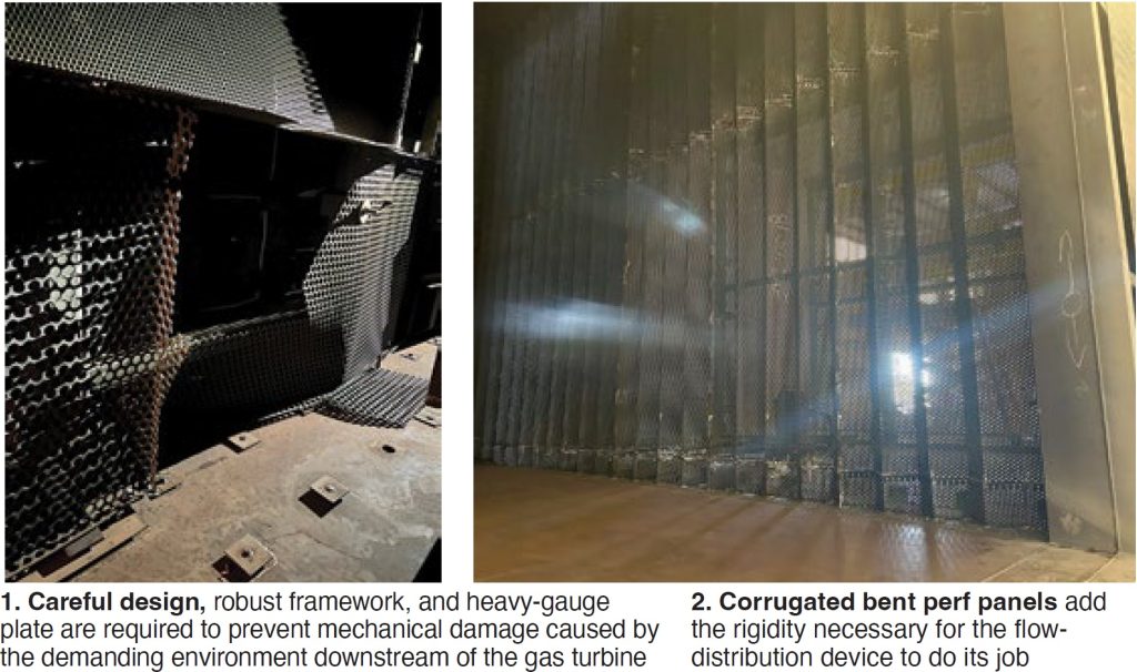
The perforated plate lives in a very torturous environment because of the high velocities, high temperature gradients, and backpressure putting mechanical and thermal stresses on the flow-straightening device and its frame. Thus, careful design, robust framework, and heavy-gauge plate are required (Fig 1). Care must be taken to manage thermal growth without binding.
Strength is important. This is why corrugated bent perf panels often are used to add rigidity to the perf-plate sheets—to stiffen them (Fig 2). Light-gauge plates and floating angle supports are not up to the task of restraining anywhere from 1 million to 5 million lb/hr of exhaust flow.
If your SCR system is not meeting expectations, consider engaging a consultant with years of relevant design and problem-solving experience to review your situation and develop a plan to improve its performance.