 CCJ ONsite’s coverage of technical highlights from the Generator Users Group’s Third Annual Conference, held in Phoenix, Aug 27-30, 2017, concludes below with the third and final installment of lessons learned and best practices shared among attendees.
Presentations and discussions are arranged in these five sections:
-
- Stator frames and magnetic cores.
- Stator windings and bus systems.
- Fields and excitation systems.
- Operation and monitoring.
- General topics (read on).
Links are provided to each of the first four sections in case you missed them. Summaries of the presentations in Section 5, which appear below, were prepared by IEEE Fellow Clyde V Maughan, president, Maughan Generator Consultants, who supplied the muscle to get the GUG off the ground in late 2015. Users wanting to dig deeper into any presentation can access the PowerPoint in the Power Users library. Note that Power Users Group is the umbrella organization serving the generator, steam turbine, combined cycle, 7F, and controls users groups.
Members of the GUG steering committee, all of whom have been with the volunteer organization since startup, are the following:
2018 Chair: Ryan Harrison PEng, lead generator engineer, ATCO Power (Canada).
2018 Vice Chair: Dave Fischli, generator program manager, Duke Energy.
Immediate Past Chair: Kent N Smith, manager of generator engineering, Duke Energy.
John Demcko, lead excitation engineer, Arizona Public Service Co.
Joe Riebau, senior manager of electrical engineering and NERC, Exelon Power.
Jagadeesh Srirama, generator engineer, NV Energy.
Mark your calendar now and be sure to attend the Fourth Annual Conference and Vendor Fair of the Generator Users Group, Aug 27-30, 2018, at the Louisville Marriott Downtown in Louisville, Ky. Follow the agenda, in development, on the organization’s website.
General topics
-
- Moisture ingress and storage mechanisms in large generators, Neil Kilpatrick, GenMet LLC
- Generator layup, Dhruv Bhatnagar, GE
- Practical experience in implementing NERC standard PRC-019, Douglas Selin, Arizona Public Service Co
- Generator maintenance considerations and robotics, Dan Tragesser and Chris Markman, GE
- Hydrogen seal-oil experience, Dhruv Bhatnagar, GE
- Coordinated frequency response, Thor Honda, Emerson
Moisture ingress and storage mechanisms in large generators
Neil Kilpatrick, principal, GenMet LLC, integrated more than four decades of metallurgical knowledge into his presentation, covering several aspects of moisture ingress on generators: problems created, moisture opportunities, capillary basics, examples of planar capillaries in generator construction, damage mechanism affected by moisture storage, and why it is so difficult to dry out these machines.
As an example of a problem with moisture ingress and storage, a large generator located in the South (think humid) was found with water actually running out from under the ID of the rings. The cause was condensation on the rotor inner surfaces and planar capillaries and connected surfaces internal to the winding.
Large generators normally are dry under operating conditions. When open and cooled to ambient temperature, there’s a tendency for moisture to accumulate on and in insulation materials. The usual remedy is to apply heat and ventilation in order to dry out the winding; this can be a lengthy process.
There are numerous moisture opportunities related to inadequate protection during shipment, storage, standby, and maintenance. Even during operation, there are opportunities for condensation from gas coolers, cooler leaks, and frame flooding. Outdoor units are a particular challenge given their exposure to weather. Hydrogen-cooled units have lower exposure than air-cooled units because of the controlled operating environment.
Capillaries behave the same whether horizontal or vertical. With dry air at the ends of capillaries, the capillaries contain only air. Increase the humidity to the point of condensation and water starts to condense inside the smallest capillaries. This occurs at about 92% relative humidity (metal temperature relative to dew-point temperature). With nearly saturated air at the ends of the capillaries, water starts to condense in small capillaries. Under saturation conditions, condensation occurs on free surfaces, and pooling begins. The capillaries will fill.
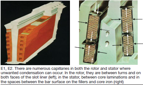
There are numerous capillaries on both the rotor and stator. On the rotor there are capillaries between turns and on both faces of the slot liner (Fig E1). On the stator, there are capillaries in the spaces between core laminations and the spaces between the bar surface on the fillers and core iron (Fig E2).
Damage mechanisms of moisture affect both metals and insulation. For generators which still have nonmagnetic retaining rings susceptible to stress corrosion, crack initiation and crack propagation occur under wet conditions. Note that retaining rings are under high stress at standstill and all other conditions. With long-term wet conditions, rust will form on steel surfaces which are bare and/or porous. Rust is hydroscopic, and will retain moisture—more opportunity for water storage.
On insulation, the major concern is for moisture on insulating surfaces. Typically, wet conditions in generators will result in low resistance to ground, and this must be corrected before return to service.
The issue of the difficulty in drying out a generator is interesting. A generator in operation tends to be inherently dry, because of the high temperature and high ventilation flow. On shutdown, there is no ventilation flow, so the entire machine becomes a large number of stagnant zones. Any stagnant zones that have some moisture content tend to become saturated. Capillary condensation will work to fill all the connected capillaries.
If the open machine is exposed to humid conditions, then the daily dew-point cycle may result in periods when the dew-point temperature is greater than the metal temperature. Condensation will occur, and the machine will take on water as long as condensation continues.
A filled capillary is relatively stable at moderate ambient temperatures and stagnant conditions. There is almost no driving force to evaporate water back out into a stagnant atmosphere at the same temperature. A significant increase in metal temperature will increase the evaporation rate by producing a decrease in local relative humidity. Significant ventilation flow should also break up the stagnant zones with the rapid inflow of dry air. For the rotor, a significant increase in shaft speed will provide a G loading which will tend to centrifuge water out of the rotor.
It is always better to keep a dry machine dry, than to dry out a wet machine. For maintenance and layup conditions, it is important to make sure that capillary condensation conditions cannot occur. Prevention can include maintaining some ventilation flow of dry air throughout the machine and maintaining temperature well above the ambient dew point; a healthy margin would be 80% relative humidity. For long-term layup, develop a system which combines fail-safe sealing, monitoring, and drying. A nitrogen blanket or dry gas feed might be considered.
Generator layup
Dhruv Bhatnagar, GE’s technical leader for generator-fleet risk management, provided the OEM’s guidelines for unit layup during non-operational conditions. Stator and rotor recommendations are the following:
-
- Stator layup for days. No recommendations for H2-cooled units if the hydrogen is pressurized. For liquid-cooled stators, the cooling-water system (SCWS) should be operational, or shut down with water drained from the winding for any layup of more than 48 hours. For air-cooled units, or H2-cooled units that are depressurized, turn on space heaters to prevent condensation.
- Stator layup for weeks or months. For air-cooled units, turn on space heaters to prevent condensation; same for H2-cooled units, but depressurize before turning on space heaters. H2-cooled units not purged should reduce gas pressure to 0.5 psig to minimize consumption. For liquid-cooled units, the winding and SCWS should be drained and vacuum-dried.
- Rotor layup for days. Rotor should be at rest with the pole axis in the vertical direction. Coat all exposed shaft surfaces with light lubricating oil.
- Rotor layup for weeks or months. Rotor should be at rest with the pole axis in the vertical direction. Megger field monthly and trend insulation resistance. A low megger indicates moisture in the generator. Inspect exposed shaft surfaces and the collector rings to ensure that the oil film is adequate.
Similar recommendations were provided for collector systems, seal-oil systems, and coolers.
In addition, the following case studies related to improper storage were discussed:
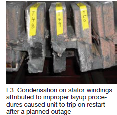
Case No. 1. Unit was in a planned outage (turbine upgrade). During restart after the outage, the unit tripped on stator differential protection. Upon inspection, damage was noted on the turbine-end series loop caps (Fig E3). The failure was attributed to condensation on stator windings.
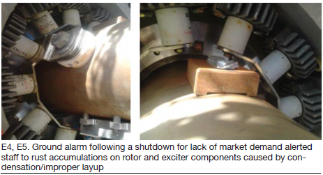
Case No. 2. Unit was shut down because of grid issues. Upon restart, a field ground alarm was activated and the unit was shut down again. Inspectors noted rust had accumulated on the rotor and exciter components because of condensation and improper layup (Figs E4 and E5).
Implementing NERC Standard PRC-019
Douglas Selin, PE, consulting engineer, Arizona Public Service Co, provided an overview of the NERC standard and the process APS uses to implement the PRC-019 across its fleet of generators. A review of the standard outlined the functional entities required to comply with the mandate, the applicable facilities, and the individual requirements which involve coordinating voltage regulator controls with the protection system and the capabilities of the equipment (generators or synchronous condensers). The time requirements for implementing the standard on a fleet of generators also was presented.
The evaluation process used by APS includes the following five steps:
-
- Identify all of the voltage-regulator limiter and protection functions for a given generator.
- Identify all of the generator relay protection functions enabled.
- Determine what coordination must be evaluated based on a comparison of the items identified in Steps 1 and 2 above.
- Perform the needed evaluation and modify settings such that they coordinate.
- Document the results in a formal report.
Several methods of demonstrating how the coordination can be reviewed, visualized, and documented were presented for most of the voltage-regulator functions that would be encountered in such an evaluation. A summary list of learnings was offered to enhance the efficiency of the evaluation process.
The effort needed to perform the coordination analysis outlined is a requirement for all generator owners. It has the benefit of improving power-system reliability by avoiding unnecessary unit trips: Generator voltage regulators act to mitigate undesirable operating conditions before relays trip the unit.
Generator maintenance considerations and robotics
Revision L of GEK 103566, perhaps better known by number than its title, “Creating an Effective Maintenance Program,” was reviewed by Dan Tragesser and Chris Markman to help owners operate their generators safely and reliably. Tragesser manages technical risk for GE’s Global Generator Product Service Engineering, Markman is product manager for generator inspections.
Six key areas were discussed by the duo—including Rev L updates, rotor removal recommendations, inspection and maintenance intervals, how intervals are determined, examples of intervals, and rotor and retaining-ring life management. GEK 103566, which was said to contain information of importance to users, can be obtained from your GE rep.
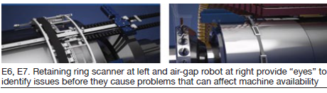
Robotic inspections were the next topic with specific references made to the OEM’s retaining-ring scanner (Fig E6) and air-gap robots (Fig E7). The speakers said robotic inspections were performed on 512 units between 2011 and 2016, with 8% having significant findings (defined as rotor removal required for repair) and half of those deferred to next outage. There were three forced outages associated with the 20 rotors pulled. Two had rotor grounds and one was forced out by a negative sequence current with arc strikes.
The speakers said electrical tests conducted on the rotors removed typically confirmed the findings of other tests or conditions—such as shorted turn and vibration. Data show robots typically find the same defects as visual inspections with the rotor out. Discussion regarding robot inspections that resulted in a rotor pull noted that more than 50% of these could have been planned for with better operations data review and outage management.
Relative to reliability, GE reported four cases of MAGIC (Miniature Air Gap Inspection Crawler) robots losing parts—including two burst bearings (encapsulated bearings are now used) and three fastener issues (redesigned). Relative to robots getting stuck, GE has emergency retrieval capability built into designs.
Also discussed was the stator cooling water system with focus on copper oxide buildup and removal.
Hydrogen seal-oil experience
GE’s Dhruv Bhatnagar returned to the podium to address the challenges associated with seal-oil systems and how to mitigate them. Challenges include the following:
-
- The seal rings themselves. Damage, contamination, improper assembly, and cocked seals all can lead to operational issues—including oil ingress.
- Float traps require manual bypass during every startup/shutdown. Improper procedures are conducive to seal-oil ingress.
- Oil contamination of the hydrogen control panel.
Seal-oil-system mechanisms and effects was the next topic. Mechanisms include cocked seals, loss of seal oil, damaged anti-rotation pin, contaminants, damaged seals, generator pressurization, clogged drain lines, improper assembly, and misoperation. Resulting effects include higher total and hydrogen-side seal-oil flow, improper liquid-level detector alarms, high float-trap oil level.
Checklists for disassembly and reassembly followed:
Disassembly. Measure rotor position from the outboard oil deflector fit to the shaft, measure the distance between the hydrogen seal casing and the rotor shaft, determine “as-found” seal clearances, inspect seals, and ensure seals are not out-of-round.
Reassembly. Inspect seals and ensure they are not out-of-round, check for any foreign material between the inner oil deflector and hydrogen seal casing, check vertical face of the end shield between the upper half and lower half for any steps across the horizontal joint, perform blue check and ensure 100% contact, check for any RTV that may have squeezed from between the upper half and lower half of the end shield, remove any RTV material that has come onto the horizontal joint of the lower-half casing, ensure seal-oil inlet feed and gas-side seal-oil drain in the end shield are clear.
The presentation closed with a case study of a unit that was offline, but pressurized and with seal-oil system in operation, when a blackout occurred. The DC system came online, but the site lost seal-oil differential pressure (DP). By the time DP was restored, the unit had dropped 10 psi in hydrogen pressure. The decrease in seal-oil DP allowed oil ingress.
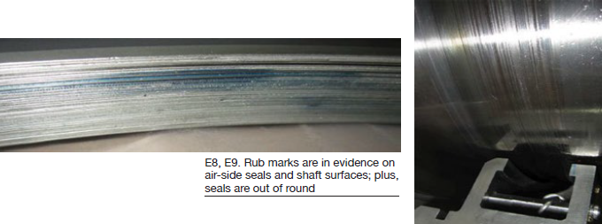
The operator received multiple liquid-level detector alarms, and low and low-low lube-oil alarms. Site personnel tried to start up the unit next day but were unable to build lube-oil header pressure. Personnel purged and inspected the generator, which was flooded with lube oil. Air-side seals and shaft surfaces were found to have rub marks (Figs E8 and E9); seals were out of round.
Coordinated frequency response
Emerson’s Thor Honda, an expert on the modernization of mechanical and electronic turbine controls, discussed the challenges associated with injecting into the grid large amounts of intermittent power produced by renewable resources. This new and evolving paradigm in electric generation has highlighted the need for synchronous turbine/generators to help stabilize system frequency.
The questions then arise: How the synchronous powerplants respond to system frequency disruptions and what changes may need to be made in order to comply with frequency response codes and standards? Synchronous generators add rotating inertia and have governors which detect frequency disruptions and raise/lower output to quickly balance generation to load (called “droop” control or primary frequency response).
These questions become more acute because tax credits and rapidly declining costs are driving ever more massive amounts of renewables power into existing transmission systems. A lower percentage of synchronous generators means less inertial response to frequency disruptions, and less inertial response means more turbine/generator response is needed. Synchronized turbine/generator droop control must give a sustained response to minimize the magnitude of frequency disruptions and maintain reliability.
NERC’s 2012 Frequency Response Initiative Report found only 30% of the generators online provide primary frequency control, and that two-thirds of those that did respond exhibited “withdrawal” or “squelching” of the response. The reason is outside closed-loop control. Since only 10% of the units online were sustaining their expected primary-frequency-control “capability,” a reliability issue arises: Balancing authorities (BAs) get a significant portion of frequency response from load and cannot predict the load response or control it (load’s inertial contribution cannot be accurately predicted).
These issues have encouraged NERC and industry efforts to improve frequency reliability, thereby making the need for government regulations less likely. One step in that direction is GE Technical Information Letter 1961, “Steam Turbine Governor Studies to Meet NERC Frequency Response Advisory,” which was supported by a webinar.
Honda closed his presentation with these recommendations for owner/operators:
-
- Verify unit-specific requirements with your BA.
- If operating in closed-loop automatic generation control (AGC), biasing may be required to pass BA compliance criteria.
- When implementing AGC bias, deep the following in mind:
- AGC will not negate droop impact on site output, which may have economic considerations.
- Ensure AGC bias is accurate and enabled accordingly.