
It happens to all of us. One day we wake up and realize, we’re not young anymore. You can, in the same breath, decide you need to do some things differently. Or, you can ignore it, and pay a larger price later.
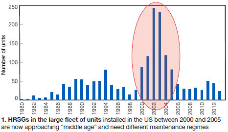
The same thing is true with heat-recovery steam generators (HRSGs). Combined-cycle plants experienced the equivalent of the post WWII “baby boom” between 2000 and 2005 (Fig 1). These units are now in or approaching the second half of their 25-30-year design life.
The need to acknowledge this reality and plan accordingly was considered important enough that the Combined Cycle Users Group (CCUG), at its 2017 conference in Phoenix at the end of August, devoted the better part of a morning to the subject so that the experts at HRST Inc could identify some the problems users could experience and possible solutions.
At an industry level, Bryan Craig noted that the general goal is to plan for and avoid similar ageing problems experienced with the fleet of fossil-fired boilers installed a generation earlier. The range of issues presented, and the photographic evidence from operating units, in the HRST slides is so extensive that users are strongly encouraged to access the original presentations at www.powerusers.org. This article gives some highlights.
Like many fossil units, combined cycles often operate in ways not designed for—that is, less baseload and more cycling and dispatch. Some of the original design materials and methods may be questionable as well.
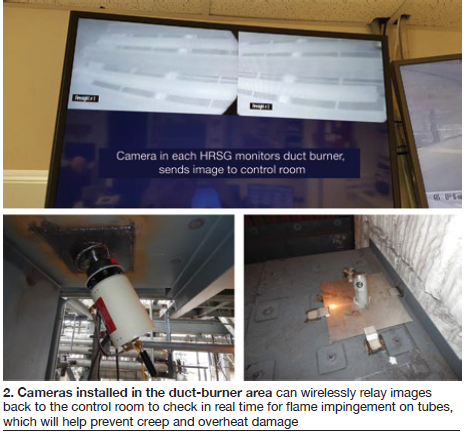
Creep and overheat damage in superheater and reheater tubes is the first problem Craig tackled. Most tube overheat incidences occur downstream of the duct burner and are caused by flame impingement. Flames should never make contact with tube metal yet they often do. Rules-of-thumb for flames are that they should be 6-10 ft long, they should be independent and separated, and reach one-half to two-thirds down the firing duct.
While users should view flames at least once daily, and preferably once per shift, through the unit’s viewports, a better idea is to install cameras in the firing duct (Fig 2) on the walls, floor, and/or ceiling and wirelessly transmit the images to screens in the control room. Damage is often worse in areas difficult to view through the casing ports.
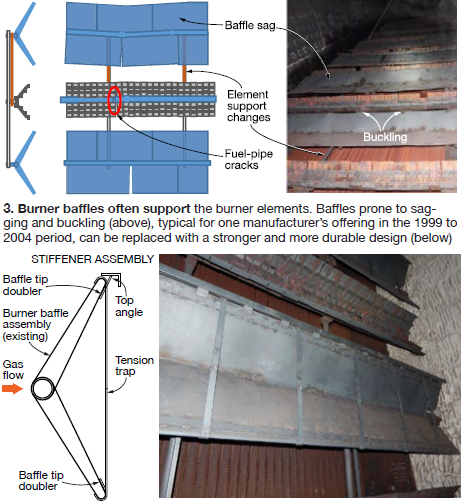
Up next were duct-burner problems, notably baffle sagging, cracking, and fluttering; flame-holder failures; coking; burner-nozzle cracking; and flow-distribution equipment failure. In the case of baffles, for example, they often sag under their own weight as the radiant heat weakens the metal. Because they also provide horizontal and vertical support to the burner elements, weakness in the baffles causes problems in the burners, such as fatigue cracks. Fig 3 illustrates the some of the issues with one type of burner and vintage, and the fix HRST has implemented.
Casings experience cracking and corrosion problems at the roof because of numerous piping penetrations, and on the sides where temperatures generally above 800F may exist. Unrepaired casing cracks can lead to graphitization and more extensive repair work. Of course, any cracks, especially in the roof, lead to rainwater ingress and insulation failures, which only compound problems with internal surface corrosion.
In the duct-firing area, there’s more insulation to protect against higher temperatures. However, when the burners are not running, this becomes the coldest area of the casing. If the temperature dips below the exhaust gas dewpoint, acidic condensation may occur, leading to rare cases of stress-corrosion cracking. High NOx environments, units with no SCR for example, are especially prone to SCC.
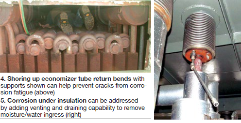
Ageing problems in economizers. Craig focused on the return-bend style of economizer design (different from panelized economizers). Much of the economizer’s weight is supported by the return bends, making them prone to corrosion fatigue. Startup thermal shock aggravates the situation. To address this, HRST has developed a retrofit support system that avoids any new pressure parts (Fig 4).
Craig offered suggestions and more robust inspection, testing, and assessments for addressing high-pressure evaporator waterside deposits and high-temperature piping. The API 579/ASME FFS-1 specification to assess “fitness for service” and remaining life should be considered for high-temperature piping. He noted that a “high percentage of welds being tested are problems.” For areas prone to corrosion under insulation, Craig suggested retrofitting vents and drains (Fig 5).
Steam drums
Part deux of the HRST trio of presentations at CCUG was handled by Lester Stanley and focused on HRSG steam drums. Stanley led off with a quick primer on steam drums, their function, and refresher illustrations, and a list of five important steam-drum components (Fig 6). Then he identified the five issues he would address: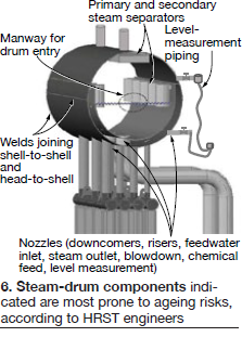
- Steam-purity degradation.
- Drum-level-measurement piping condition.
- Nozzle weld cracking.
- Shell weld cracking.
- Manway sealing reliability.
“Steam-drum performance and steam purity were probably carefully tested at commissioning,” Stanley said. But in the second half of life, “age is affecting the mechanical condition of the drum internals.” This can result in excessive water carryover. Specifically:
- Primary and secondary separators get fouled with rust.
- Fouling occurs in the final separators, increasing velocity and impairing moisture separation.
- Gaps appear in the final separators, allowing wet steam to pass through.
- Separator housing and supports fail from stress and also allow wet-steam bypass.
- Errors occur in drum-level sensing, leading to higher water levels and less volumetric space for moisture to drop out; this is usually caused by level-transmitter calibration/compensation.
Detecting these problems is best done through more frequent saturated steam sampling, and even continuous on-line monitoring.
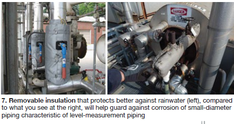
The condition of drum-level piping is critical for accurate level sensing. Age-related risks include plugging of sensing lines with debris and corrosion of small-diameter external piping. The latter risk grows with increased downtime. Removable insulation blankets exacerbate rainwater ingress. Solutions are to inspect under insulation more frequently and consider use of removable insulation with better protection against rainwater (Fig 7).
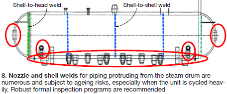
The focus for nozzle and shell weld cracking is the high-pressure (HP) drum but all steam drums should be inspected, Stanley urges. Although the intermediate-pressure (IP) drum is the least susceptible to weld cracks, it’s easy to include it in the inspection program for the HP and LP so you “sleep better at night.”
On/off cycling drives weld cracks in the HP drum. This causes temperature differentials between the shell and its nozzles because the drum pressure cycles across a wide range, such as from 0 to 400 psig. Problem is, there are numerous thick nozzles and shell welds in an HP drum (Fig 8). In the LP drum, internal diameter (ID) pitting, leading to cracks, is the notable threat.
Stanley then spent considerable time reviewing several relevant inspection techniques and offered suggestions for how to prepare for and set up an inspection program. Perhaps the overriding message was, don’t try this at home; in other words, retain an experienced, qualified crew.
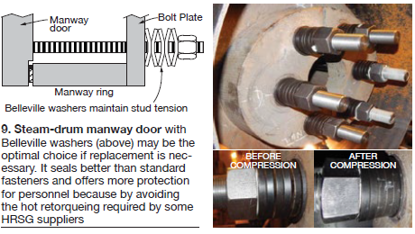
Manway reliability was Stanley’s final topic. The ageing risk is the deterioration of the gasket sealing surface over time from cleaning and removing old gasket material, impurities in water residue, gouging from steam cutting or closing damage, and corrosion during downtime. The gasket sealing surface has to be smooth but not “polished” smooth, and there’s more precision necessary in the serrations (like an album surface) than you might think.
There are a few specialists with the proper tools to re-machine the sealing surface, but sometimes replacing the door may be the best option. This allows you to ease the problems associated with achieving the minimum sealing stress for various types of gaskets. The proper seal stress is difficult to achieve with studs and a torque wrench because drum pressure in operation provides the last increment of stress necessary. Many HRSG OEM manuals require hot retorquing procedures, which are dangerous and should be avoided.
Stanley thinks a manway door with Belleville washers is a better design (Fig 9). Eliminating hot retorquing allows you to install a steam shield for additional personnel protection. Stanley noted that the Belleville washer design has gone through several years of demonstration in the field.
Drones
Your plant cred may be lacking these days if you don’t have a presentation on drones at your user group meeting. Natalie Teuchert, completing the HRST triumvirate, filled that bill at the CCUG. The first of Teuchert’s slides reviewed the basics of using drones at the plant—FAA regulations, training and certification, and some things to think about regarding drone construction.
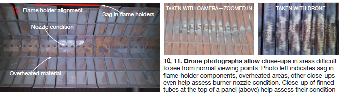
The second part was replete with rather dramatic comparisons of what you “see” with a drone inside your unit versus what you can detect visually looking up from the floor, including photos of burner condition (Fig 10), close ups of burner nozzles, hairline cracks in flame holder castings, bent igniter tubes, close ups of finned tubes at the top of a tube panel (Fig 11), and many others.
Teuchert’s main conclusion is that drones allow you to inexpensively inspect areas prone to ageing issues more frequently, and thus avoid costly problems down the road. CCJ