


BY Dave Lucier, PAL Turbine Services LLC
Turbine Tip No. 5 from the PAL Turbine Services O&M solutions library applies to General Electric Frame 5 models L, LA, and M equipped with Oilgear fuel pumps, Frame 5N machines with New York Air Brake pumps, and 5P and 5PA gas turbines with Roper Pump Co equipment.
This is a follow-up to Turbine Tip No. 4. That article dealt with a failing pump operating at 100% speed (full speed/no load, 5100 rpm). This article looks at a fuel pump that does not function reliably at “firing” speed (20% of rated speed).
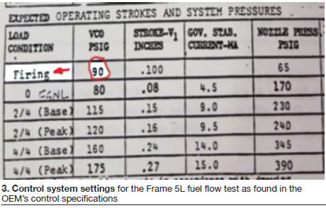
GE control specifications provide valuable information for testing at firing speed. For a Frame 5L operating at 1000 rpm, expected fuel flow from the flow divider to the 10 combustors is 2.2 gpm. This means each combustor should receive 0.22 gal (approximately one quart) for a 60-sec firing attempt.
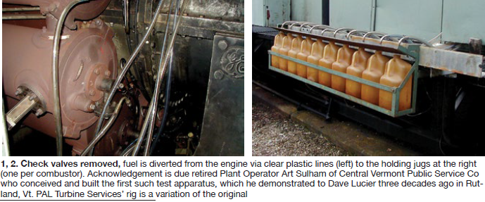
First steps: Remove all 10 check valves from the engine and divert fuel flow (Fig 1) to the test rig (Fig 2). By re-routing fuel via the clear plastic lines, the “false firing” attempt will collect all the fuel. Without check valves, fuel pressure is negligible.
Safety tips: Disconnect spark plugs and flame detectors before the test. Also, warn personnel that the CO2 fire protection system remains charged in standby.
The test is conducted as follows:
1. Start the gas turbine with selector switch 43 in CRANK and run up to 1000 rpm.
2. Confirm firing time is set for one minute on timer 2F.
3. Move the switch to the FIRE position, and time for 60 sec using a stopwatch.
4. Fuel is diverted to the 10 jugs shown for the “false firing” period (Fig 3). The fuel flow expected is 10 × 0.22 = 2.2 gpm. Thus, each container should collect approximately one quart of fuel. Final step is to empty the fuel lines into each jug. Note that the expected maximum rated fuel flow with the engine operating at 5100 rpm is 37 gpm.
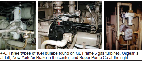
Figs 4-6 show the three types of fuel pumps (Oilgear left, New York Air Brake center, and Roper Pump Co right) GE used on its Frame 5 gas turbines during the US production period from 1965 to 1990.
The test described works equally well for all GE Frame 5s manufactured during this 25-year period. In all cases, fuel flow at “firing speed,” which depends on the engine model, will be less than 3.5 gpm.
Of course, Frame 6B and Frame 7B, C, and E machines all require more fuel flow at firing speed, but not so much that this test rig would not be useful. Roper Pump Co and IMO Pumps are found on the 6B, Denison Hydraulic equipment on 7Bs, and Warren Pumps on 7C and 7E engines.
In conclusion, the value of this test is in confirming that the fuel pump and flow divider are working properly. The check valves removed should be disassembled, cleaned, reassembled, and tested. Electricians should test the spark plugs and UV flame detectors.
This definitive test is easy to perform and produces indisputable results. PAL Turbine Services recently brought its test rig and a spare fuel pump to a Frame 5 outage in Pennsylvania. Good thing. The existing pump was tested and found lacking in fuel flow at the 1000-rpm firing speed. It was replaced with the spare (reconditioned) pump and tested before system recommissioning.
Lesson confirmed: Proper preparation is critical for maintaining planned outage schedules. CCJ