Turbine Tip No. 14 from the PAL solutions library applies to General Electric package power plants (PPP) incorporating MS5001 and MS6001 gas turbines
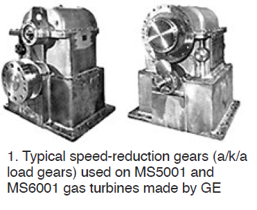
GE offered these two gas-turbine models requiring speed-reduction gearboxes to drive 2-pole ac generators (Fig1):
-
- The MS5001 package power plant manufactured by the OEM in Schenectady from 1960 to the mid-1980s.
- The MS6001 cogeneration engine also made in Schenectady—from 1978 to about 1988.
These plants had gas turbines operating at approximately 5100 rpm, with speed-reducing gearboxes driving generators at 3600 rpm. Good alignment of the gas turbine to the load gear was critical for vibration-free operation of driver and driven equipment at those speeds.
Today, laser alignment often is used when servicing these PPPs. But because the gas turbines have liberal allowed alignment tolerances, Pond & Lucier LLC believes laser technology in this application is engineering “overkill.” You can save money by bringing in an ex-GE field engineer with the knowledge and skills to do it the “old-fashioned” way.
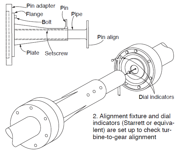
The skill requires the use of various dial indicators and the “how to” knowledge used during the original installation by a GE engineer. A tubular version of the alignment fixture (Fig 2) can be used with various dial indicators (Starrett or equivalent) to measure and establish the deliberate vertical offsets shown in GE technical publications.
Alignment of the load gear to the gas turbine takes into account the following factors:
-
- Relative vertical growth of the gas-turbine exhaust (including the exhaust hood and the No. 2 turbine bearing) with respect to the load gear when at baseload.
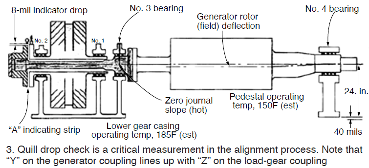
- Proper loading of the common bearing shared by the load gear and generator rotor. This alignment is commonly known as the “quill drop” A shim under the generator pedestal bearing was chosen to assure the front-end weight-bearing of the generator rotor (field) rotor (bearing No. 3 in Fig 3). This may have to be changed to get the proper “drop.”
- Bearing centralization for the generator rotor, as measured at the front of the load gear. This includes a “crank check” to assure the straightness of the quill shaft.
GE specifies the amount of vertical offset between the turbine and high-speed gear shaft flanges. Of course, the load coupling must be removed and the alignment fixture installed to accomplish this measurement. With the fixture attached to the turbine-end flange and dial indicators reading on the face and rim of the pinion-gear flange, the turbine should be lower than the gear by approximately 50 to 60 mils. That would be a total indicator runout (TIR) of 100 to 120 mils with the rim dial indicator initially set at zero at the top 12 o’clock position.
Note that these offset numbers will vary depending upon the GE model: MS5001K, L, LA, M, N, or P; the MS6001B will be somewhat different.
It is important that once the load coupling is installed after alignment, it not be internally bound. Radial clearance can be checked as shown in Fig 4.
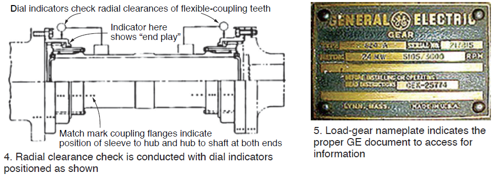
GE provides data sheets and nameplates with the gas turbine. Example: In Fig 5, the nameplate indicates that information for the S-624-A reduction gear is in publication GEK-25774.
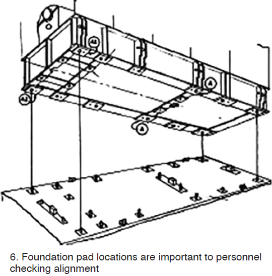
The generator foundation supports are shown in Fig 6. The calculated “move” takes into account the vertical and horizontal moves for all the pads, with shim changes required on each pad to achieve the “perfect” move. A well-trained engineer can follow the GE specifications to elevate the generator to the proper level using the principles of trigonometry and geometry learned in high school.
In conclusion, look to GE’s gas-turbine instruction books for the document addressing field alignment. This is not “rocket science” and does not require lasers to accomplish. Hire a grey-haired or balding ex-GE engineer who installed a Frame 5 or 6 gas turbine in his or early years in field engineer services.