Plant managers diligently pursue O&M strategies that have a high probability of success for keeping their electric generating assets in service throughout the “must-run” season—this to assure a profitable year. Deciding on what inspections are necessary to access the information needed for reliable decision-making is part of the challenge. Today’s meager budgets do not allow for inspecting everything you’d like to check with the latest diagnostic tools available. You have to pick and choose based on a review of operational data, equipment idiosyncrasies, and your instincts honed over the years.
Consider your heat-recovery steam generator. Many combined-cycle plants do not have a boiler expert on staff—one who is relatively knowledgeable about HRSG water treatment and damage mechanisms, welding, and metallurgy. Given the stationary nature of this equipment, damage, such as cracking at tube-to-header welds, may not be identified until it has reached the point when an outage is necessary.
Thus, given access to industry experience with HRSGs of a design the same as, or similar to, yours, perhaps you can develop a meaningful inspection plan that involves frequent visual checks by staff and detailed inspections by third-party experts every couple of years or so. The experience of others, beyond that provided by colleagues, can be gained through participation in industry meetings—such as the monthly virtual sessions conducted by the HRSG Forum—where you have the opportunity to discuss your concerns with attendees.
Tube-to-header welds. Consider inspections of tube-to-header welds for a moment. You can do a crawl-through and look for signs of cracking when the HRSG has been offline long enough to cool. But you could miss cracks because they tend to “heal” as the unit cools down and it’s unlikely you would see cracking on the back side of the tube in any event. But there could be other visual signs of leaks that you would see—possibly steam scoring on a tube’s external surface.
Magnetic particle inspection (MT) is better than a visual-only check, but surface preparation is necessary and you probably won’t be able to see more than about 200 deg around the tube surface. Phased-array also is a possibility, but it too requires surface preparation and space restrictions might not allow complete access around the tube.
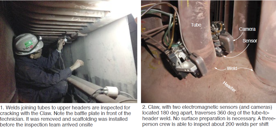
A better choice might be TesTex Inc’s “Claw.” It examines tube-to-header welds for cracking at both the toe of the weld and in the weld (Figs 1 and 2). Typically used for inspections in the HP superheater and reheater sections of the HRSG, it relies on the so-called Balanced-Field Electromagnetic Technique (BFET) for reliable identification of indications. The device is used for header diameters of 4 in. and larger. The claws are able to examine the tube-to-header welds for tube diameters of 1.5 to 3 in.
Tube-wall thinning. Using a proprietary Low-Frequency Electromagnetic Technique (LFET), TesTex technicians can examine HRSG finned tubes from the outside to detect and quantify internal pitting, wall thinning attributed to flow-accelerated corrosion, and under-deposit corrosion (Fig 3). Benefit of LFET is that access holes don’t have to be cut in the tubes to conduct an inspection.
TesTex’s Shawn Gowatski says LFET is very reliable for locating pits of ¼ in. diam and larger, and wall loss in excess of about 20% of the tube wall thickness. This type of damage typically is found in the economizer and back-pass sections of the HRSG, warning of impending issues that can be corrected before a forced outage might be required.
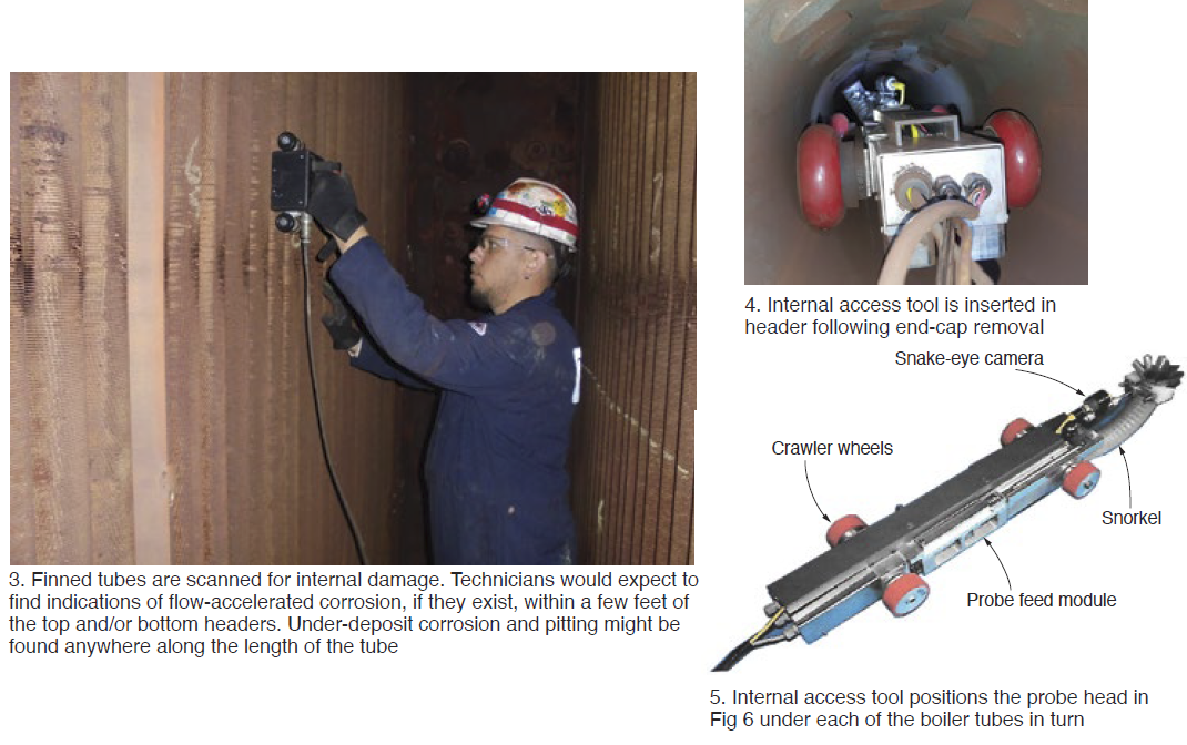
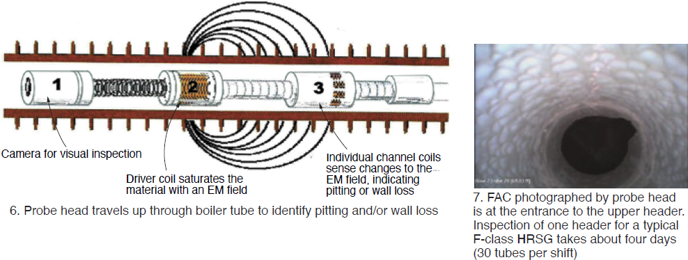
A more exacting inspection of tube internal condition is possible with TesTex’s Remote Field Electromagnetic Technique (RFET) using the internal access tool. The crawler (Figs 4 and 5) is inserted in either the upper or lower header after the end cap is removed and the RFET probe, equipped with a camera, is moved through individual tubes to detect wall thinning and make a video recording of the 360-deg internal surface. Probe travels at 2 to 3 in./sec (Figs 6, 7, and video). Current header-to-header tube-length limit is 70 ft. A benefit of using this tool is that it is able to examine the full lengths of all the tubes in a header.