The spate of lawsuits filed in the aftermath of the 2021 winter storm that left millions in Texas without power for days and sent natural-gas prices soaring to their highest levels in years—up nearly 17,000% in some cases, according to a Wall Street Journal report—testify to the value of having dual-fuel gas turbines as part of the generation mix.
The well-recognized ability of gas turbines to generate power at high efficiency and with minimal emissions is only one important attribute of these flexible machines. In emergencies, they can start within minutes and when equipped for black-start service can be a major factor in grid restoration as they first did immediately after the Great Northeast Blackout of 1965.
The most-recent Texas experience suggests a re-examination of the financial logic associated with buying gas-only engines may be in order.
In many instances, gas-only is an appropriate choice: Capital cost is lower than for a dual-fuel machine; no backup liquid-fuel system is required; environmental and safety requirements are reduced; overhauls are less time-consuming and costly; training of plant personnel is simplified. In some cases, the presumed advantages of gas-only operation convinced owners to remove liquid-fuel hardware from their engines and abandon in place or remove their oil-storage and fuel-transfer infrastructure.
However, business conditions in the electric-power industry are always in a state of flux. Today, with renewables in regulatory favor, it can be difficult to extract a profit from fuel-fired assets in some areas of the country if they are not equipped to start and run reliably on oil when gas is not available.
Reliable operation demands attention to detail in fuel-system design and equipment selection, which are impacted by such variables as the time allowed for startup on oil or for transfer from gas to oil, the financial penalty of a failure to start on oil, reliability/availability requirements of the off-taker, etc. But be confident that there are commercially available dual-fuel solutions to meet your needs. Success depends in large part on your ability to achieve the following:
-
- Assure reliable hot-gas-path (HGP) hardware is installed in your engine.
- Design a fuel system capable of providing the level of reliability on liquid-fuel starts and transfers needed to meet contractual requirements.
- Maintain backup liquid fuel in top condition.
HGP hardware. This probably is the easiest box to check. All turbine OEMs, as well as many third-party service providers, can evaluate the ability of your HGP components to perform reliably in dual-fuel operation. Lifetimes of airfoils and other critical parts are less when oil is burned instead of gas, but the number of oil-fired hours experienced by the typical dual-fuel engine will have minimal to no impact on parts life.
An informal survey by the editors indicates that more than a few dual-fuel engines have not operated on distillate oil for periods as long as years—other than to periodically test the ability of their turbines to run on liquid fuel.
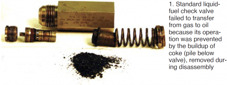
Fuel system challenges. Oil temperature is, perhaps, the variable of greatest importance in the design of standby fuel systems. Reason is that distillate remaining in check valves and piping after firing on oil oxidizes at about 250F—or less. The resulting coke coats check-valve internal surfaces (and fuel lines as well) and restricts the movement of valve parts. Once this occurs, a check valve may not open and close properly until it is overhauled.
The most common trip during fuel transfer is believed to be on high exhaust-spread temperature—caused almost exclusively by check valves hung-up on coked fuel.
Engine compartments with GE frame turbines typically reach temperatures in the 250F to 300F range, according to a few users contacted by the editors. This puts uncooled fuel-system components at an elevated risk of coking.
Given that liquid fuel lines are secured in close proximity to the turbine casing, sections of which can hit 500F, you can have oil baking at a temperature well above the coking point in some locations.
There are steps engineers can take at the design stage to mitigate the risk of coking in standard fuel-system components. For example, install a recirculating liquid system, move fuel lines away from the casing to reduce their exposure to very high temperatures, gravity-drain oil lines after use, etc. Regarding the last, one thing to remember is that oil does not drain completely and coke builds up in thin layers over time.
However, this buildup isn’t the biggest problem. When layers of coke break loose, the cause may be an event which impacts multiple fuel lines simultaneously. Examples include liquid-fuel check-valve chatter and rapid expansion or contraction of fuel lines, both of which can dislodge material instantly. Rectifying the problem may require removal of fuel nozzles to address high exhaust-temperature spreads and related trips.
Depending on contractual requirements, another possible downside to the draining of fuel lines is that the system has to be primed and purged of air prior to burning oil again or a false start is likely to occur. Priming, of course, takes time, which you may not have.
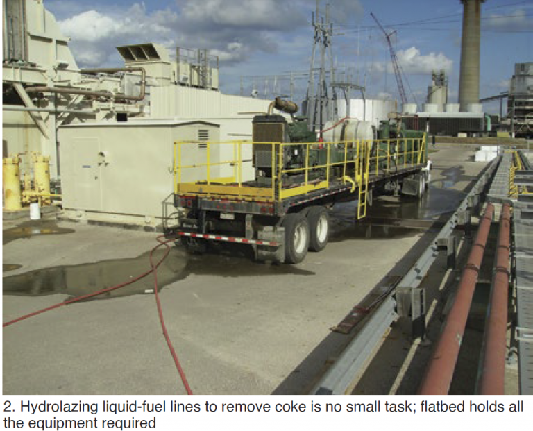
Another point to remember: If your fuel valves and lines get plugged, the coke must be removed or the affected components replaced. Fig 1 shows how much coke was removed from one standard liquid-fuel check valve during an overhaul. Fig 2 illustrates the considerable effort required to cut through and flush coke from fuel lines of a 7EA DLN-1 unit using the hydrolazing technique. It took about a week’s effort to return the machine to service.
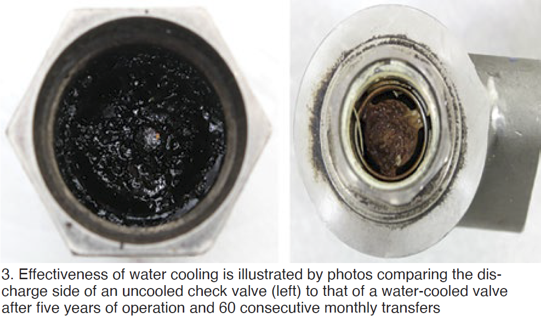
The gold standard for liquid-fuel systems in dual-fuel plants is water cooling, to prevent coke formation in fuel lines and valves while the engine operates on natural gas and oil is maintained up to the combustor, assuring a seamless transfer to distillate when required.
Liquid-fuel quality must be maintained at the highest level to prevent water and other contaminants from entering the fuel system. Recent experience reported by users on the effectiveness of storage-tank side-stream filtration systems, based on technology used to restore turbine hydraulic and lubricating oils to top condition, illustrate the importance of avoiding the “fill and forget” attitude that prevails at some plants.
The ability of these systems to remove water entrained in stored fuel is beneficial to the health of cast-iron flow dividers still metering fuel to combustors at some plants.
Water-cooled liquid-fuel system
Schuyler McElrath, the industry’s most vocal proponent of water-cooled liquid fuel systems, assures owner/operators that JASC’s® Gen3 system is capable of approaching 100% reliability during oil starts, and on transfers from gas to oil.
On a recent call with the editors, he ran through the company’s nearly two decades of product improvements and the reasons for his enthusiasm. McElrath pointed to five consecutive years of service and 60 consecutive transfers for JASC’s water-cooled liquid-fuel check valves before an unsuccessful attempt (Fig 3) and seven years of experience with water-cooled three-way purge valves without loss of system reliability.
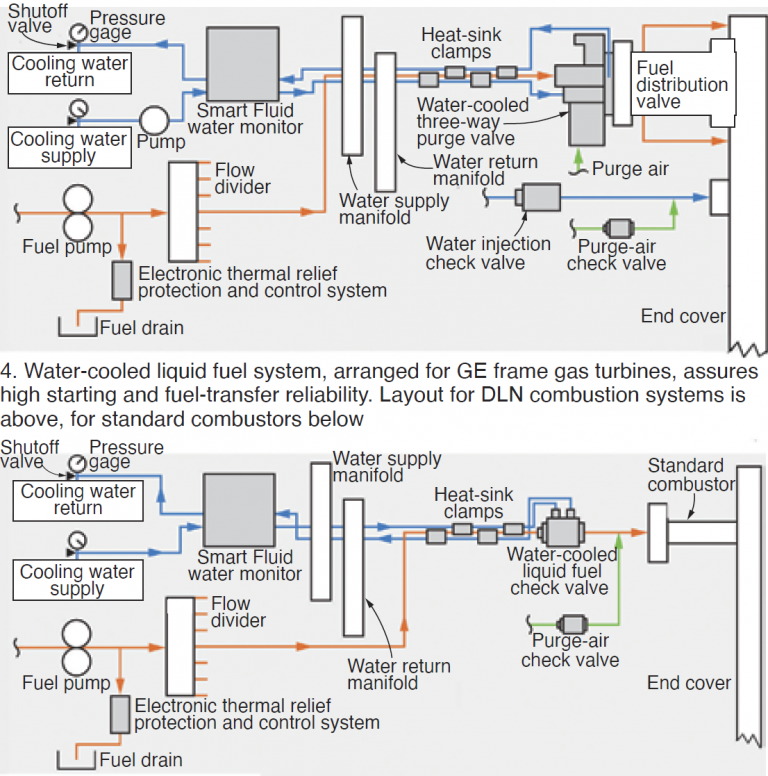
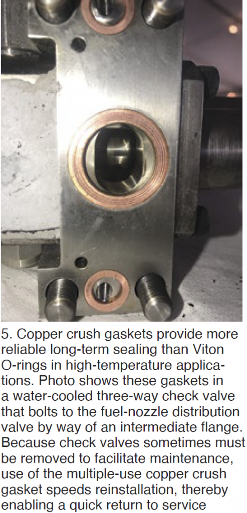 The water-cooled three-way purge valve replaces the uncooled version of the valve, which could plug with coke formed by “cooking” of the liquid fuel when gas was burned. Perhaps the most significant Gen3 improvement on these valves was the elimination of heat-related O-ring failures on liquid-fuel and purge-air connections through the use of copper crush gaskets (Fig 5) in place of Viton.
While Viton is designed for high-temperature applications, after long-term exposure to heat they lose elasticity, take a set, and crack. The typical result is leakage at joints because of metal expansion and contraction during operation.
JASC’s experience is that copper crush gaskets will survive high-temperature exposure indefinitely with no change to sealing integrity, making them more compatible with today’s extended maintenance intervals. Plus, these gaskets can be made, broken apart, and remade multiple times before requiring replacement.
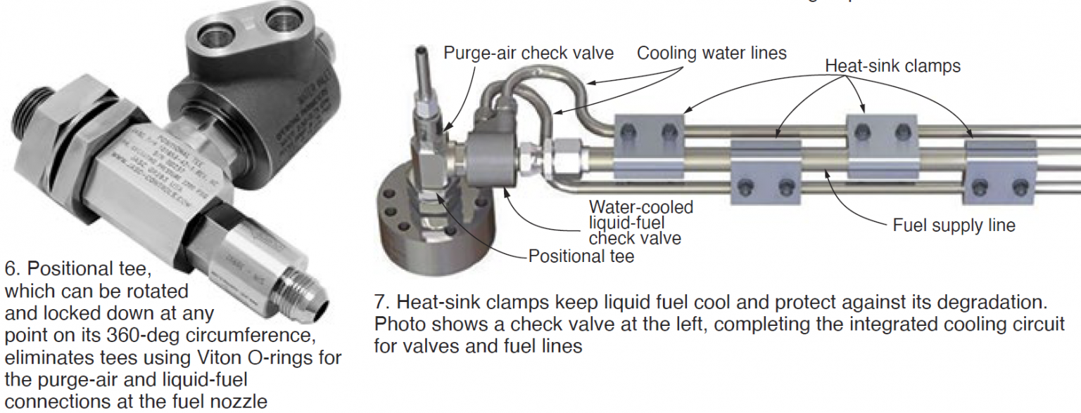
So-called positional tees (Fig 6) are another Gen3 improvement associated with the three-way purge valve. They eliminate tees using Viton O-rings for the purge-air and liquid-fuel connections at the fuel nozzle, opting for copper crush gaskets instead. Positional tees get their name from the fact that they can be rotated and locked down at any point on their 360-deg circumference. The benefit: Three HGP cycles or 12 years of leak-free operation in both peaking and baseload applications.
Heat-sink clamps (Fig 7), located just upstream of the three-way purge valve in Fig 4, keeps the liquid fuel system primed from the stop valve to the fuel controls and ready for immediate dispatch. The clamps protect stagnant diesel fuel against viscosity changes which foul fuel control seats and can transition distillate oil to solid coke during extended periods of operation on natural gas.
Water-injection check-valve Gen3 improvements focus on metal-to-metal sealing, thereby eliminating the degradation of elastomeric materials formally used and preventing leakage while on standby during operation on natural gas. Eliminating water-system evacuation on standby avoids exhaust-temperature spreads/trips when water injection is reactivated for emissions control.
The smart fluid monitor shown in the system diagrams was redesigned for the Gen3 system to accomplish the following:
-
- Measure water supply and return flow discrepancies down to 0.1 gpm.
- Programmable shutoff range of 0.1 to 1 gpm.
- Ability to monitor up to four turbines remotely.
- Standalone control or output can be integrated into the turbine control system.
- Monitor and control cooling-water flow and temperature. A critical function of the smart fluid monitor is to protect the liquid-fuel system against low temperatures associated with paraffin dropout. Recall that wax can impede fluid flow and cause a failure to start.
Liquid-fuel quality
Contaminants introduced into your liquid fuel during transportation can require a substantial cleanup effort if foreign material remains in the oil for a prolonged storage period. Reason: Some contaminants will catalyze the fuel degradation process, compounding the problem.
Having a filter ahead of the storage tank capable of trapping large quantities of water (particularly saltwater, the largest single source of sodium contamination so detrimental to HGP parts) and sediment before they enter the tank is important. Also critical to fuel quality is periodic—read weekly—bleeding of water from the bottom of the tank. This is especially true in warm, humid regions of the country. Remember that oil tanks are vented and they breathe.
Plants monitoring the condition of their backup fuel sometimes are surprised by the poor quality of oil at the bottom of their tanks—say the last 5 ft or so. This generally is not problematic given the floating suction systems typically in use today—that is, until you have to burn the dregs. It doesn’t take much sludge-type material to cause a failure to start or to trip a high-performance gas turbine. The financial penalties could be significant.
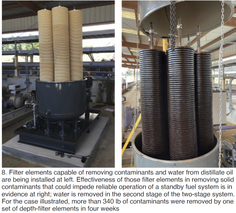
CC Jensen Inc’s Technical Manager Axel Wegner, expert in the cleanup of turbine lube and hydraulic oils, has been promoting at user-group meetings for several years the idea of using similar technology to maintain backup-oil quality with a slipstream treatment system on the storage tank. Results from the first two installations (one 1-million-gal tank, one 4-million-gal tank) at gas-turbine peaking and combined-cycle sites, just in, are encouraging (Fig 8).
Wegner told CCJ ONsite that, based on current experience, an appropriate cleanup system for a standby oil tank might turn over the inventory once a month to maintain the fuel quality desired. For a plant burning only diesel (no gas) the system probably should be designed to process oil at 110% of the consumption rate, he added.
One user told the editors that he received only two responses to his RFQ for a diesel-fuel cleanup system, purchasing one each from CC Jensen and Hy-Pro Filtration.