 Presentations by owner/operators are the lifeblood of every user-group meeting. There is value in presentations by vendors, of course, but when a user colleague shares experiences, best practices, and lessons learned everyone listens—you can tell by the questions asked and the follow-on discussion generated.
There were five user presentations at the 2017 meeting of the 7EA Users Group. The editors were present for four as reflected by the summary notes that follow. The fifth was an overview by a utility engineer on his company’s experience in converting its gas turbines to MkVIe control systems. To dig deeper, you can access the presentations on the organization’s website. You’ll have to register if not already a member.
Dovetail coating in-situ.
Dovetail wear and tear caused by excessive time on turning gear and operation at a TG speed conducive to damage is an annual agenda topic given the 7B-EA fleet’s high percentage of simple-cycle engines required to be “on the ready” by grid operators. The pounding caused by bucket and wheel contact in the dovetail region with each revolution—so-called “bucket rock”—gets worse over time, as clearances open up.
The possible consequences of operating a unit with bucket rock include loss of sealing pins, loss of chrome carbide wear surfaces on shrouded buckets, slight radial rubs, overstressing of wheel dovetails, and possible twist-lock un-staking. The speaker suggested his colleagues take the following steps to correct bucket rock:
-
- First, install progressively larger bucket-shank seal pins.
- If wear exceeds the scope of correction by the largest shank seal pins, build-up the bucket dovetail by spraying with nickel aluminide (maximum recommended coating thickness is 15 mils). Note, too, bucket tip shrouds may need rebuilding of the chrome carbide wear area.
- Dovetail wear beyond the maximum restorable thickness on the bucket requires wheel replacement. However, the speaker did say that development projects are under way to identify a reliable wheel restoration technique.
The user presented a case history on the elimination of bucket rock in the first stage of his engine. First step was to check bucket gaps at four positions along the platform. Most were over the recommended limit of 180 mils specified in TIL 1049, “B- and E-class Gas-Turbine Wheel Dovetail Material Loss.” Many were in excess of 0.200 in., one as high as 0.217 in. The TIL presents three options:
-
- Bucket dovetail spray modification.
- Wheel dovetail spray modification.
- Wheel replacement.
Additionally, first-stage material loss was determined as specified in TIL 1049. Measurements were taken with gauge pins, slightly larger than the size called for in the OEM document—0.219 in. versus 0.21875. The results all were within TIL limits, indicating the wheel had not reached end of life.
Bucket-rock measurements also were taken, using a dial indicator at the side of the platform while manually rocking the bucket to its limit and recording the total indicator travel. Rock recorded at 12 positions on the wheel ranged from 0.138 to 0.160 in. with the average 0.150. The speaker said he was told by a shop person with deep knowledge of rotors that 0.085-in. rock is the targeted value when spray coating a wheel.
The user’s plant opted to spray-coat the first-stage wheel with nickel aluminide given the engine’s current mode of operation with long periods on turning gear. The spray repair took five shifts after buckets were removed; work was done with the rotor in place. New replacement buckets were installed after completion of the spray repair. Plant rates the project a success.
Rotor exchange program.
Five of the six 7EAs at a 6 × 3 combined-cycle cogeneration plant serving an industrial facility were rapidly approaching the OEM’s stated 200,000-hr maximum rotor life for its baseload frame engines. The machines, all manufactured in 1992, were steam-injected and had averaged 182,741 actual fired hours. The high-hours engine had 188,460 service hours.
The owner evaluated the three rotor-exchange options listed below, considering several vendors in the process.
-
- Purchase both turbine and compressor rotors as new.
- Purchase seed rotors (compressor and turbine) and refurbish based on fired hours of each unit.
- Basic seed-rotor (compressor and turbine) replacement.
GE was selected to provide the seed-rotor exchange program based on rotor availability, cost, refurbishment time, and technological expertise. Key points in the OEM’s program were the following:
-
- Extend 7EA rotor fired hours from 200,000 to 300,000 and starts by 1500 to 5000.
- The OEM would provide two seed rotors, refurbish three of the plant’s rotors, and provide a spare rotor with a storage container. Compressor seed rotors would be bladed, turbine rotors would have buckets supplied by the plant and installed at the GE shop.
- A 60-day schedule was planned for rotor refurbishment.
Work scope and other important details included these:
-
- Full teardown inspection using ultrasonic, eddy-current, mag-particle, fluorescent penetrant, and visual procedures, plus hardness testing.
- Replace compressor rotor blades in stages 14 to 17.
- Replace compressor turbine, and unit rotor assembly bolting.
- Inspect and repair dovetails in compressor wheels 14 to 17, stage-16 rabbet fillets, and stage-17 impeller blades.
Note that replacement of compressor stator blades and turbine buckets and nozzles were not included in the rotor exchange project. Any other deficiencies identified in the existing turbine and compressor rotors would be categorized as “extra work.”
Project completion was planned for year-end 2017. At the time of the user-group meeting in October, the extra work—certainly of importance to anyone considering a rotor exchange—included the following:
-
- Field service charges for reaming of dowel holes and alignment of four units.
- The compressor for one unit was in bad shape and required this additional effort:
- De-blading and re-blading of rows 1 to 13.
- Patch-ring repairs on four rows.
- Turbine rotor rabbet crack repair.
- New turbine-rotor forward and aft stub shafts.
- New second-stage compressor wheel.
- New turbine wheels.
- An additional seed rotor made necessary by an unfit-for-duty compressor found in one unit.
One of the lessons learned: Don’t expect things to go the way you planned on a project of this magnitude, even having experienced manpower and putting forth maximum effort. You likely will identify issues no one thought possible. Perhaps the biggest surprise here was the finding of excessive bucket rock on one of the turbines.
The GE shop reported this for the first stage and the turbine rotor was returned to the plant without buckets, the owner believing a new set of first-stage buckets would correct the problem. It didn’t. Plan B was to have the new buckets coated to reduce the dovetail gap. But on further inspection, excessive rock also was found in the second and third stages. In the end, all three turbine wheels were replaced at significant extra cost.
A table presented by the speaker showed that the outage time projected for the unit with the wrecked compressor (last bullet point above), budgeted at 720 hours, would actually be about 4000 hours (unit overhaul had not been completed before the meeting). For the other engines, the actual outages wound up taking an average of 40% more hours than planned, in round numbers.
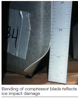 R1 compressor ice damage.
A Canadian user reported on a compressor ice damage investigation that was of interest to virtually all attendees (photo). Keep in mind, ice can form in a gas turbine compressor at an ambient temperature above freezing. The speaker explained this with several slides on the physics of ice formation at the beginning of his presentation. He also discussed the various types of ice and how they differ. Specifically, precipitate icing— such as hail, ice crystals, snow, freezing rain—and condensate icing—such as rime, glaze (clear), and frost/hoarfrost.
If you’re shaky on ice science, be sure to access this presentation on the 7EA Users Group website. It’s easy to understand and you can become an “expert” of sorts in short order.
The user’s root cause analysis focused on the following potential causes of ice damage:
-
- Plant staff did not verify the wash water system was positively isolated and drained after each compressor cleaning. The water wash procedure was updated to ensure positive drainage of the wash-water manifold.
- Inspections for leaks in the inlet ductwork and filter house were conducted, but no signs of water ingress were found.
- The anti-icing (AI) system did not prevent ice from depositing and growing on air-intake surfaces. The details in the slides specific to the GE system are recommended viewing for anyone with a similar system and issues, and anyone planning on protecting his or her plant’s gas turbines in this manner.
The AI portion of the presentation began with a description of the inputs to the control system (inlet temperature and humidity) used by GE de-icing logic to control the inlet bleed heat (IBH) charged with preventing ice formation. Problems identified included the following:
-
- Thermocouple noise, which was an easy fix by enabling a low-pass filter in the software (this is defaulted in normal control when the system is set up).
- Poor IBH valve control because of the installed position feedback on the positioner. An upgraded valve positioner solved this problem.
- Dew-point sensors were supplied by the OEM with the wrong range software. The instrument manufacturer corrected this by increasing the dwell time through the auto-purge sequence of the humidity sensor.
During the ensuing discussion it became apparent that the de-icing control provided by GE did not shut off until the ambient temperature rose above the set point—about 40F. The ambient temperature falling below the ice-formation temperature (too cold to carry moisture that would form ice) did not shut off the IBH (running at about 10%), regardless of how much colder it got. This results in a significant reduction in efficiency and output when operating at cold temperatures outside of the ice-formation physics.
Best practice: A user commented during the discussion that he and his colleagues had found a significant water entry point in the inlet ductwork. The bolting supplied during unit installation for clamping flange gaskets on the inlet “key” slot was bottoming out and not properly sealing the joint when the flange bolts were torqued. This permitted water entry into the inlet duct which could cause icing at low ambient temperatures.
Clashing update, rotor cracking.
A user with perhaps more experience on clashing in 7EA compressors than anyone else in attendance reported that one of his affected units was retrofitted with GE’s new-design S1 and S2 blades and showed no evidence of clashing after 42 fired starts in the last year. Photos revealed pristine airfoils
He also reported R17 flat-bottom slot cracks on two 2001-vintage units. One had 2877 fired hours, 675 starts, and 24 trips, the other 2490 fired hours and 557 starts. The latter had indications of similar length in 51 of the 56 slots. Very little blending was needed to remove them.