Stator endwindings in resonance can fail when improperly damped or braced
By Bill Moore, National Electric Coil
Stator endwinding resonance and high levels of endwinding vibration are a significant issue that affects many generators and can lead to premature conductor strand fatigue, cracking, arcing, and eventual failure. This can occur because of insufficient or faulty bracing systems, a lack of bracing or blocking materials, or loose or dry ties.
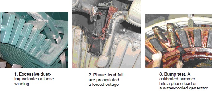
In many cases, loose endwindings have areas of dusting or greasing. Dusting (Fig 1) typically is observed as a white area, caused by insulation-material particles that have abraded away. Greasing is similar: The insulation particles from dusting mix with oil, forming a grease-like substance.
In some cases, visual evidence of high vibration levels cannot be observed. This is often true in the phase leads that join the endwinding series connections to the bus rings. (The phase leads are often a challenge to adequately brace.) Further, because of the many layers of tape, conductor cracking can occur without any outward sign—until a forced outage occurs (Fig 2).
Stator endwinding dusting, vibration, and resonance can be highly influenced by winding geometry. One example is stator bars that have long extensions or overhangs cantilevered from the end of the stator core. If not supported properly, these extended portions can experience high levels of vibration, because of the high electromagnetic forces.
Two key monitoring and diagnostic tools are needed to fully evaluate and correct stator endwinding vibration and resonance. These include the stator winding resonance, or bump test, and vibration monitoring with transducers.
Endwinding bump test
An endwinding bump test uses accelerometers placed on the stator winding, special computer software and computer, and a calibrated impact hammer. The hammer is used to bump the endwinding, causing it to vibrate. The vibrations are then measured and analyzed (Fig 3).
The purpose of performing impact or bump testing on generator endwinding baskets, phase leads, and circuit rings is to identify resonances that would be readily excitable by the electromagnetic forcing frequency (120 Hz in the US).
The mode shapes of the stator winding are determined from the analysis of the impact data collected by the accelerometers. For 2-pole generators, the N=2 elliptical mode of the stator winding should be sufficiently removed from double the operating frequency (120 Hz).
A buffer, or “exclusion zone,” is recommended to assure the N=2 elliptical mode of the winding does not drift close to the 120-Hz forcing frequency. Action is recommended when the N=2 mode is found within the range of 115 to 135 Hz for 60-Hz generators.
Also of concern are individual phase leads and individual end turns that are either resonant or are characterized by high responses at or near 120 Hz. It is recommended that corrective action be taken when end turns or phase leads are found to be independently resonant in the range of 115 to 135 Hz for 60-Hz machines. The number is biased high and away from 120 Hz, because the natural frequency typically drops to a lower value when the winding is heated and when bracing components wear and the winding loosens.
Bump testing typically includes the following tests:
- Reciprocity.
- Modal.
- Frequency response.
Reciprocity testing is used to determine if the endwinding is well-consolidated and behaving like a monolithic structure. Accelerometers are placed opposite the bump location. As the basket is impacted, the reaction at the opposite location is captured. The impact location and transducer locations are then reversed. This is done at 12:00 and 6:00 and also at 3:00 and 9:00. If responses are similar, the basket is well-consolidated.
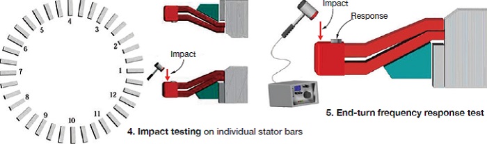
Modal testing is performed by measuring the frequency response at selected points on a structure to an excitation force (impact) applied to a single point on the same structure (Fig 4). An alternative is to measure the response at a single point, compared to impacts at various selected points on the structure. The test determines the basket’s natural frequencies and corresponding mode shapes. To perform this test, the following is done:
- Select a minimum of 12 equally spaced points around the circumference of the basket near the end-turn knuckles.
- Radially impact the basket at one of the 12 points and measure the response to the impact at all 12 points.
- Perform modal analysis to determine the basket’s resonant mode shapes and their respective frequencies.
The frequency-response test is performed by measuring and recording the frequency response of an individual end turn or phase lead to an impact applied to that same end turn or phase lead. The test determines the individual end-turn and phase-lead resonances, as well as overall response characteristics (Fig 5). Experts recommend that the test be performed in both the tangential and axial directions.
To perform this test, do the following:
- Mount an accelerometer on the end turn in the knuckle region. For phase leads, mount the accelerometer on the phase lead.
- Radially impact the corresponding end-turn or phase-lead coil in close proximity to the accelerometer.
Endwinding vibration monitoring
There are several endwinding vibration monitoring systems on the market today. Each is made up of transducers (typically 12 total for the generator—six at each end) and fiberoptic cable that safely transmits the signal from the transducer, through the generator, to the signal conditioner box, and then on to the analyzer (Fig 6).
The fiberoptic accelerometer (FOA) is non-conducting and immune to electromagnetic interference, which is essential in a high-voltage stator winding.
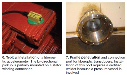
Each FOA transducer must be securely mounted to the end of the stator coil or phase lead in such a way that it can measure vibrations in the radial and tangential directions (Sidebar). The FOAs are attached to individual fiberoptic cables, which are routed to a single frame penetration port at each end of the generator. In hydrogen-cooled units, this port is a welded pressure connection (Fig 7). Since it has to maintain the hydrogen pressure integrity, while allowing the cables to exit the tank, installation of this port requires a certified welder. The cables then run from the connection port to a signal conditioning box, and then on to a programmable monitor.
The monitoring system can measure endwinding vibration during unit operation. If high vibration is detected, load can be reduced, or plans can be made to shut down the unit and perform corrective action to lower the vibration levels. High vibration levels can lead to strand cracking in the stator bars, winding failure, and a forced outage.
Although both the bump test and online vibration monitoring are valuable tools, there are limitations. For example, problems can occur if the endwinding structure is not well- consolidated. During the bump test, an unconsolidated end winding will not provide a distinct natural frequency, because individual stator bars will vibrate at different levels and the FOA transducers may be installed on bars that are not vibrating at excessive levels.
Remember, because of cost, not every single stator bar is instrumented with a transducer. Making sure the end winding is well-consolidated and behaves as one “ring-like” structure is essential for both the bump test and vibration monitoring.
Building and maintaining the endwinding as a monolithic, homogenous structure, is difficult because it consists of many components, and many different materials—including copper conductors, mica insulation, resin, glass ties, glass epoxy blocking, metal braces, and fiberglass rings.
Each of these materials has different properties; for example, they vary in stiffness and coefficient of thermal expansion. Such differences can make it challenging to ensure the stator endwinding has, and maintains, a distinct natural frequency. However, through proper bracing and blocking of the end winding, it is possible to make it well-consolidated.
While the bump test provides very valuable information, it can only be done offline and typically when the unit is near ambient temperature. Frequencies can shift to lower values when the unit comes up to temperature, as materials soften and become less stiff.
Although vibration monitoring while the unit is running is certainly valuable, determining whether the stator winding will vibrate excessively before it goes into operation is a necessary step. It is somewhat analogous to lateral and torsional vibration analysis done on the rotor shaft as part of the original design. This analysis assures that the final shaft machined shape will not operate in detrimental critical-speed zones.
The same is true for the endwinding. The bump test can help assure that the stator winding will not vibrate at excessive levels when the unit is put in service. The test is not as precise as a lateral or torsional frequency analysis, since the exact shape of the endwinding can vary somewhat (coil installation variance) and material amounts (resin, ties) and properties change with temperature.
Transducer lessons learned
The prototype turbine/generator application of one independent transducer manufacturer was made about 12 years ago. Their system is now present on over 250 installations. Results from a comparison of 50 different installations, are summarized below:
• Vibration levels of from 50 to 410 µm (2 to 16 mils) peak-to-peak were observed.
• Endwinding vibration levels were high on small units—those under 200 MW.
• Endwinding vibration levels are more controlled on the largest units—500 MW and above.
• Turbine-end vibration levels were similar to collector-end levels.
• Radial vibration levels were higher than tangential.
• No significant differences were found between 2- and 4-pole machines.
• Mechanical frequencies (50/60 Hz) were, in most cases, lower than the electromagnetic.
Safe vibration levels
In estimating expected vibration levels, keep in mind the two interacting mechanisms that cause endwindings to vibrate at 120 Hz. The first is the net dynamic distortion of the endwinding itself, by the Lorentz forces acting on the conductors; the second, the radial magnetic pull on the core which, in a 2-pole generator, deforms the core into a synchronously rotating ellipse.
By itself, this base motion can cause as much as two mils or more of the total vibration. Depending on the amount of separation of the endwinding global elliptical mode’s (or other excitable local mode) natural frequency from 120 Hz, the forced vibration levels attributed to these mechanisms can be magnified.
There has not yet been sufficient experience to create a valid rule-of-thumb to discriminate between normal and worrisome vibration. But the data suggest 125 µm (5 mils) or less of radial vibration is safe, while 250 µm or higher may be too high and not safe for long-term reliability. Phase leads, because of their geometry, may vibrate at higher levels, but should remain well-damped. Over the years, as data accumulate, it will become possible to refine these values, including adjustments for types of endwinding support, number of poles, and type of generator duty.
Vibration exclusion zones
As noted earlier, a recommended exclusion zone for the bump test should be in the range of 115 to 135 Hz for a 60-Hz system. This zone applies to all local natural frequencies (such as might be found by means of a bump test on a bar or phase lead), but only to one global natural frequency—the N=2 ring mode or elliptical mode in the case of a 2-pole machine.
The reasoning behind these limits is as follows: The degree of magnification of the forced vibration level of a given mode depends on the damping associated with the mode, as well as the proximity of the mode’s natural frequency to the 120-Hz driving force. A rough estimate of the magnification factor can be made, based on the forced-vibration behavior of a simple, single degree-of-freedom viscously damped system. For such a system, operating at 10% of critical damping and forced at 120 Hz, the magnification factor is two or greater for natural frequencies between 100 and 166 Hz.
It is significant that the magnification factor for a low-tuned system (with the elliptical mode’s natural frequency below the forcing frequency) approaches zero as the natural frequency decreases. Conversely, the magnification factor for a high-tuned system is always greater than unity and increases as the natural frequency decreases.
Since many of the materials in a typical endwinding support system are epoxy or polyester-based resin composites, it is probable that there is some decrease in the stiffness of the endwinding structure with increasing temperature. Also as the generator is operated and the winding undergoes thermal cycling, the endwinding tends to loosen, and the overall stiffness decreases.
These factors are the underlying basis for the skewed exclusion zones. For low-tuned modes, natural frequencies as high as 114 Hz—as determined by bump testing at room temperature—are permitted. This is based on the assumption that the natural frequency of concern will decrease and move away from 120 Hz at operating temperature. But for high-tuned modes, the upper boundary of the exclusion zone is set much further away from 120 at 135 Hz because it is assumed that the natural frequency will move downward toward 120 Hz at elevated temperatures.
Because of the tendency of the natural frequencies to drift downward, high-tuning is inherently more risky than low-tuning. Fortunately, in the case of the mode of concern (the global elliptical mode in a large 2-pole generator), it is generally much more difficult to design a high-tuned endwinding, than one that is low-tuned. For a well-consolidated 2-pole generator endwinding, the only global natural frequency of concern is the elliptical mode (the N=2 ring mode).
While other natural ring modes with three (N=3) and four lobes (N=4) are often found near or in the exclusion zone, these modes generally will not be excited by the elliptical or N=2 force pattern. This is because of a mismatch in the force patterns. The higher harmonic displacement patterns result in no net energy being added to the higher modes.
Concluding remarks
Stator endwinding vibration and deterioration has been a major concern on large turbine/generator windings for many years. Efforts to improve endwinding performance have been hampered by lack of instrumentation capable of safely and conveniently measuring endwinding vibration levels on generators in service. Such instrumentation is now available, and along with endwinding bump testing, pro-active steps can be taken to mitigate stator endwinding resonance and high vibration levels.
The industry now has the knowledge and experience to implement corrective actions based on the test results. Note that blocking, tying, and bracing are specialized jobs that require an engineering evaluation, diagnosis, and repair by knowledgeable individuals and companies.
As more endwinding vibration data for given generator sizes and types are made known, realistic vibration-level and resonance acceptance criteria will undoubtedly become standard.
Acceptance criteria for both the bump test and endwinding vibration levels were mentioned here, but many variations in machine type and design exist. These variances can influence the acceptance criteria and anticipated results. Each generator should be treated individually. It is necessary to perform a combination of tests and inspections to avoid issues related to stator endwinding resonance and high vibration.
Case studies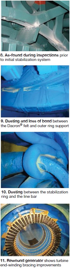
1. Gas/turbine generator
This case history describes how two strategies were used to correct vibration and resonance issues on a troublesome stator endwinding in a 204-MVA, 18-kV, hydrogen-cooled generator. The machine, manufactured in 2001, began commercial operation in 2004. It had a loose endwinding, which resulted in dusting.
Problems on similar machines have been identified in the industry, and, in those cases, the use of ‘dry ties’ contributed to the problems. A photo of the original winding bracing system showed a significant lack of endwinding support. In fact, no endwinding support back to the core/frame existed on the turbine end of the machine and very little bus-ring support was observed. Photos 8-10 were taken during various inspection and repair outages.
Several attempts to stabilize the endwindings were made by the owner. The first attempt to repair the broken and loose ties was made in October 2007. Additional blocking on the endwindings was also added. However, bump tests confirmed that, while there was improvement in the circuit rings, the endwindings still had a significant response in the operating range of 114 to 126 Hz. Next step: Install an endwinding stabilization system on both ends of the generator during a scheduled four-week outage. The results of a second bump test where within acceptable limits.
However, annual inspections since May 2008 found continual degradation in endwinding supports—as evidenced by dusting.
In 2010, an inspection found dusting between the bar/support ring ties, between the endwinding diamond spacers, between the circuit rings, and circuit-ring ties/blocking. There was a notable increase in dusting in areas with a loss of bonding between the bottom bars, Dacron felt, and the support ring on the outer most support ring. Dusting was even noted between areas of contact with the stabilization ring, which was added in 2007. At this point, it was clear that the endwindings were sufficiently loose that the only cost-effective, long-term solution would be to rewind.
The generator was rewound by NEC during a seven-week outage in April/May 2012. The rewind included a new endwinding support system, which incorporated several modifications to provide better stiffness to the structure.
As part of the rewind scope, a pre-rewind bump test was done to characterize the condition of the stator endwinding. Modal testing indicated that the elliptical (N=2) mode shapes of both the turbine end and exciter end were low-tuned, meaning that the N=2 modes were below the 120-Hz excitation frequency. End-turn response amplitudes were below 0.05 g/lb, with the exception of 12 series connections.
However, the phase-lead responses displayed high amplitudes within the 120-Hz region on the top phase leads 1, 2, 3, 4, and 5 and on bottom phase leads 5 and 6. The bump test results indicated that the support structure of the endwinding was inadequate, and although the endwinding N=2 mode was outside of the exclusion zone, the overall looseness of the winding had to be corrected to avoid a possible shift in resonance.
The unit was rewound with a completely new endwinding bracing system, designed to adequately support the end turns during a transient fault and provide sufficient rigidity to withstand steady-state electromagnetic forces, but still allow the necessary axial differential expansion when the unit comes up to temperature.
Significant improvements to the original endwinding bracing system included the addition of turbine-end braces (no braces existed in the original winding), an increase in the number of braces at the exciter end, tapered blocking at the series connections, additional bus-ring blocking and tying, and an inner nose ring (Fig 11).
After the rewind, a second bump test was completed. The modal testing indicated that the elliptical (N=2) mode shapes of both endwindings remained low-tuned. All end-turn response amplitudes were below the requirement standard of 0.05 g/lb. All phase-lead response testing showed consistent results, with only one bottom phase lead initially being above 0.05 g/lb with a resonance of 0.08 g/lb at 128 Hz. Once blocked and tied, the resonance dropped to 106 Hz, and was well-damped below the 0.05-g/lb criterion.
Results showed clear improvement in the support of the endwindings, which are acting as linear, monolithic structures. Despite all the additional support and blocking, each endwinding was low-tuned with the elliptical (N=2) modes, well below the elliptical forcing frequency at 120 Hz and outside the 115-135-Hz range criteria. Once blocking was added to the bottom phase lead, all phase-lead responses were within tolerance. Additionally, the local response testing showed low amplitudes of response.
Fiberoptic transducers also were installed on the exciter-end phase leads to provide a real-time condition report of endwinding vibration. Initial transducer readings ranged from a low of 3.0 mils to a high of 5.5 mils at approximately 90% of full load. The bottom phase lead that initially bump tested high, was then blocked and tied further, resulting in vibration readings of 3.0 mils. Although the 5.5 mils of vibration for the one phase lead is higher than desired, it is well-damped at below 0.05 g/lb. Therefore, no concerns exist.
Readings will be archived and trended over time. Also, during the next outage, the generator will be opened. The phase leads will be visually inspected and bump-tested to see if any shift in frequency has occurred, or if additional blocking and tying is necessary.
2. Steam turbine/generator
A 301-MVA, 18-kV generator driven by a steam turbine also had issues with dusting, like the unit described above. The machine was manufactured in 2001 and placed in service three years later. Dusting was observed during the first inspection in May 2008 and annually thereafter. Removal of the rotor was planned for October 2011 to fully assess the endwinding condition and to develop a plan for stabilization.
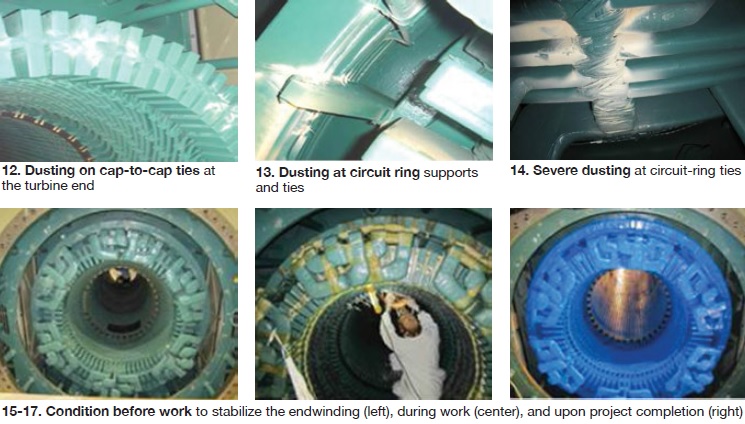
Upon inspection, extensive dusting was found on all circuit-ring blocking and ties, and main/neutral-lead blocking and ties. Circuit-ring taps to the line and neutral bars were poorly braced, resulting in circuit-ring movement transmitted to the stator bars—as indicated by dusting. Extensive dusting also was found on the turbine end of the winding at the bar-to-ring ties to the support rings, and at the series cap blocking and ties. Some of the dusting is shown in Figs 12-14.
Based on these findings and an initial bump test, NEC made several recommendations. First, it was necessary to perform a wedge tap test, replace all loose ties and blocking, install endwinding stabilization rings on both the exciter and turbine ends, re-block, and tie phase and neutral- bar/circuit-ring taps. Also recommended was that a final bump test and modal analysis of the endwindings, connections, and circuit rings be performed to ensure the effectiveness of the stabilization effort. This work was planned and executed over a scheduled nine-week outage (Figs 15-17).
The endwinding stabilization effort improved the dynamics of the endwinding, although not as significantly as in the first case study (above) which involved a rewind. Ongoing monitoring and testing of this unit is planned, but it is clear that the winding life has been significantly prolonged by the repairs. CCJ
Bill Moore is director of technical services for National Electric Coil. Prior to joining NEC in 1997, Bill held plant management positions with Florida Power & Light Co. A licensed professional engineer in Ohio and Florida, he started his 35-yr power industry career as a generator design engineer with Westinghouse Electric Corp.