
Borescope inspections offer insights for condition-based maintenance
Plant managers, particularly those responsible for combined cycles, need all the help they can get. Their jobs have become ever-more demanding because of increasing regulation, relentless corporate pressure to reduce costs, loss of experienced personnel to retirement, etc. One hands-on plant director recently told the editors that he never made it down to the deck plates during the last engine overhaul because of the mountains of NERC, OHSA, EPA, company, and other paperwork that had him handcuffed to the desk. First time that ever happened, he said.
In addition to all the regulatory and company forms and reports that demand “immediate” attention, there’s a steady stream of OEM advisories flowing into the plant. Those require the plant manager’s attention as well, because properly working equipment is critical to a positive bottom line.
Perhaps one of the reasons top management doesn’t have a deeper appreciation for plant personnel is because the OEMs have senior staff convinced that after a relatively short “break-in” period, their gas turbines will work well until the first overhaul—years away in most cases. Then perform as planned until the following overhaul, and so on. Anyone who really knows generating equipment is aware that the classical “bathtub curve” doesn’t apply here and damage occurs over time depending on the mode of operation, quality of parts and repairs, degree of unrealistic expectations, general “abuse,” etc.
There are many variables that can be monitored to warn of impending problems—such as exhaust-temperature spreads, compressor discharge temperature and pressure, power output, lube-oil temperature, etc. However, there are things that can go wrong in an engine that cannot be identified easily—or at all—using operating data. These include spalling of coatings on hot-section parts, tip rubs of turbine buckets, clashing of rotating and stationary airfoils in 7EA compressors, etc.
Your “eyes” in such cases are inspection experts equipped with the latest borescopes and nondestructive examination (NDE) tools. Technicians with intimate knowledge of an engine’s internals are the plant manager’s first line of defense against catastrophic damage: They know what to look for and where to look.
The leading inspection companies are continually developing new techniques for identifying issues earlier than had been possible previously. Some also have tools for taking corrective action in-situ. User-group meetings are ideal venues for catching up on such advancements and experience with them.
To illustrate, what follows is a summary of the inspection results and recommendations presented by Rod Shidler, president, and Mike Hoogsteden, field service manager, Advanced Turbine Support LLC, Gainesville, Fla, this fall at the CTOTF™ and 7EA User Group meetings. Advanced Turbine Support is believed to conduct more inspections of gas turbines than any other third-party services provider.
(click thumbnails to see larger images)
Tip-cap inspection
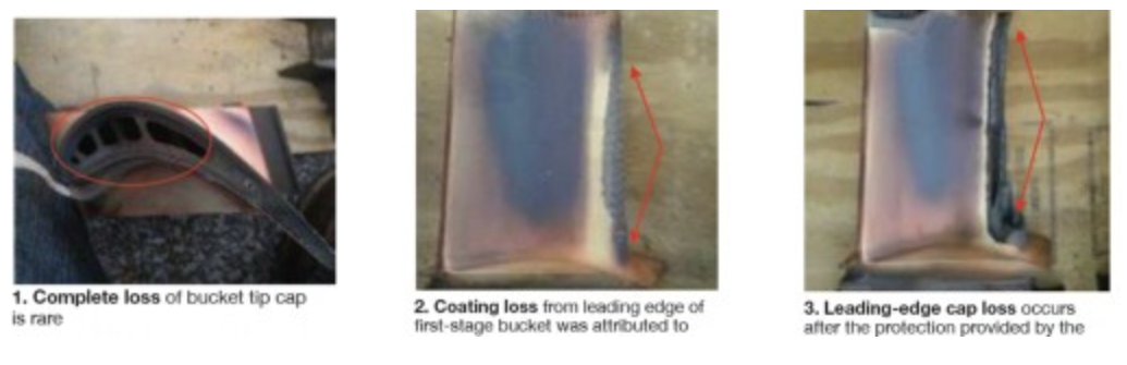
Shortly after the 7EA User Group meeting at the end of October, Hoogsteden reported that Advanced Turbine Support had perfected a specialized method for inspecting, without turbine disassembly, 7FA first-stage buckets for tip-cap damage or loss (Fig 1). This is important because such damage is conducive to a reduction in airfoil cooling. When that occurs, the expected end result can be a loss of coating on the leading edge of the affected bucket (Fig 2), or in extreme cases, the loss of the entire leading edge (Fig 3).
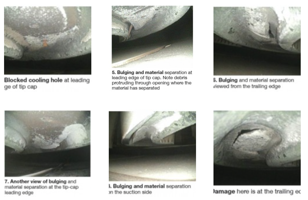
Advanced Turbine Support technicians inspected all 92 first-stage tip caps on each of six engines in the early fall. Four units were fine, two had buckets with damaged tip caps. Checking first-stage tip caps adds about four hours, depending on findings, to a typical 10- to 12-hr engine inspection. Hoogsteden said bulging and material separation of the tip cap, and plugged cooling holes, are likely precursors of eventual failure.
It’s unlikely that damage to a particular tip cap would be reason to remove the GT from service, but the findings serve as an alert and enable users to better schedule an outage for repairs. Figs 4-9 illustrate the damage found in six different buckets in the two affected machines.
Clashing: No TIL yet
The annual conferences of the 7EA Users Group traditionally begin with a State-of-the-Engine report by Advanced Turbine Support LLC. At the 2012 meeting, Hoogsteden’s presentation indicated that the number of issues identified annually in the ageing fleet is increasing. It’s more important than ever, he said, to perform inspections regularly and properly to prevent “issues” from developing into catastrophic losses. Then the service manager stressed the need for owners’ engineers to review promptly documented findings and to develop and implement programs to mitigate identified risks.
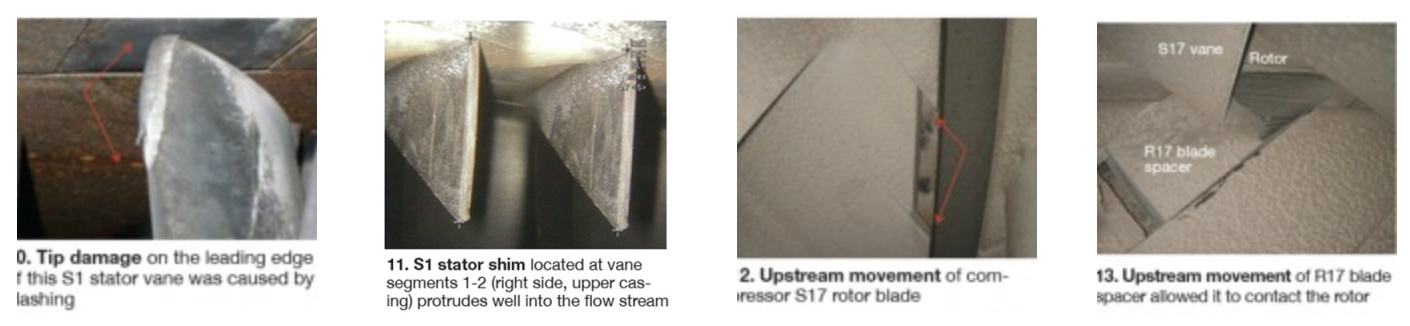
For many attendees, the highlight of the presentation was Advanced Turbine Support’s five-step clashing mitigation procedure that Hoogsteden introduced to the group. Recall that clashing—the term used to describe contact between rotating blades and stationary vanes in Frame 7 compressors (Fig 10)—has been a hot topic for years at the 7EA meeting.
Advanced Turbine Support inspectors have documented clashing damage to the trailing edge of R1 rotor-blade platforms and the leading edge of S1 stator vane tips for the last five years. More importantly, accurate measurements of the damage have been taken over the last three years and records maintained for each affected vane, using the OEM’s stator-vane numbering system. In several cases, data have revealed increases in clashing damage over time.
Check for clashing damage during your regular semi-annual or annual borescope inspection. Absent a Technical Information Letter (TIL) on how users should address clashing damage, Advanced Turbine Support offered the following procedure:
- Perform an in-situ red-dye penetrant inspection on the trailing-edge platforms of rotor blades, stator-vane tips, and on the convex side of stator vanes where damage is in evidence.
- Blend/crop in-situ the affected airfoils. The extent of the repairs is determined by the type of damage identified during the first two steps.
- Apply in-situ an approved lubricant/rust inhibitor to the platforms of damaged stator vanes. Note that current industry thinking is that vane lock-up attributed to rust and other airborne debris is at least partially responsible for clashing.
- Monitor/trend results. Appropriate intervals for follow-on inspections would be determined by the extent of the mitigation process implemented.
TIL review. Hoogsteden spent most of his time at the podium discussing what Advanced Turbine Support believes are the OEM’s most important TILs regarding the 7EA compressor. Much of this information had been presented previously and covered in past issues of CCJ, but more than half of the 120 or so attendees were first-timers and the review was particularly valuable. The following is a list of the TILs covered and the issues they addressed, with publication dates in parentheses:
- 1132-2R1, spring and thrust washers for variable inlet guide vanes (Dec 15, 2004).
- 1562, stator-vane shim migration (Jan 30, 2007).
- 1854, compressor R2 and R3 tip loss (Aug 27, 2012).
- 1090-2R1, R17 blade movement (Mar 3, 1993).
- 1744, stator-ring rail and CDC hook-fit wear in stages S17, EGV1, and EGV2 (Sept 27, 2010).
Photos incorporated into Hoogsteden’s comments on typical IGV damage, illustrating rubs against the inlet bellmouth and bending of inlet guide vanes, had already appeared in CCJ ONsite. Shim migration has been discussed extensively over the last several years in the CCJ. That information also can be accessed by using the Google-like search feature. Hoogsteden gave the group an Advanced Turbine Support rule of thumb: When a shim protrudes 250 mils or more into the flow stream (Fig 11), it almost always can be removed. If removal is not possible, the shim should be trimmed flush in-situ with the stator-vane platform.
Tip grinding is not necessarily the solution, he added, recalling indications of cracking on 18 blades during the unit’s first inspection following tip grinding of that blade row in the shop. A red-dye check adds only a little time to a regular borescope inspection because all R1 and R2 compressor blades, and about 85% of the R3 blades can be accessed in-situ.The service manager mentioned that the week prior to the 7EA meeting, an Advanced Turbine Support inspection team found ½-in. cracks on two pristine rotor blades—that is, there were no tip rubs and no discoloration in evidence. Hoogsteden said the company’s recommendation was to do a dye- penetrant exam during each inspection to monitor crack growth.
Regarding TIL 1090-2R1, Hoogsteden said the biggest concern is how much the R17 rotor blade is moving forward. The Friday before he addressed the 7EA users, an Advanced Turbine Support inspector reported that upstream movement of an R17 rotor blade spacer allowed it to contact the rotor, despite double staking. Blade and spacer movement shown in Figs 12 and 13 was 100 mils; maximum allowed is 10 mils.
7FA bucket platform cracking
Put first-stage-bucket platform cracking on your inspection hit list, Shidler and Hoogsteden told owners of 7FA Models 7231 and 7241 at CTOTF’s 2012 Fall Turbine Users Conference in San Diego. They mentioned a relatively rare “find” the previous weekend: The pressure-side platform crack shown in Fig 14. Although Hoogsteden said Advanced Turbine Support had found cracking previously on the pressure side of 7FA first-stage turbine bucket platforms, the amount of separation shown here together with the offset is not typical.
Cracks that go unnoticed are virtually sure to grow and could lead to liberation of a portion of the platform as the photo in Fig 15 indicates. Downstream turbine damage can be expected. Figs 16 and 17 illustrate that skilled inspectors can get up close to any flaws identified for precise measurements. This information then can be referred to engineering for further analysis and decision-making.

TIL 1854
TIL 1854 was issued in late August: Have you read it, yet? If not, don’t worry. It was rated “optional” by the OEM. TIL 1854 addresses tip losses on 7EA Rows 2 and 3 compressor blades caused by heavy rubs and/or corrosion pitting. Conclusions drawn from operating experience and engineering analysis suggest that casing distortion over time, as well as hot restarts after shutdowns of between one and eight hours, are responsible for the rubs.
Damage ranges from scoring of the casing to rolled material at the top of the airfoil. Fatigue damage caused by heat generated during rubbing is conducive to blade-tip liberation when high-cycle fatigue conditions exist. A user told the editors that the foregoing has been known for years. Inspectors manning the booth for Advanced Turbine Support confirmed that fact and brought up some borescope images on the company laptop showing an R2 tip liberation and rolled material that had been taken two years earlier (Figs 18-20).
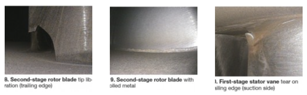
The reps said this particular unit had three R2 tip liberations and had one R1 stator vane damaged by flying metal. Team Advanced Turbine Support suggested dye-pen inspections of airfoils that had suffered tip rubs to gauge the level of damage. A quick read of 1854 did not bring to light any such recommendation by the OEM. Advanced Turbine Support said it could dye pen R2 blades during a borescope inspection.
TIL 1724
Another thing Advanced Turbine Support representatives were telling 7FA owner/operators at the CTOTF fall conference was that they could have corrosion in the quarternary fuel annulus, which is located in the forward combustion casing of late-model frames—those equipped with DLN2.0 and DLN2.6 combustion systems.
Inspection and cleaning were recommended by TIL 1724 to reduce the risk of operational issues—including elevated dynamics, high exhaust spreads, and even unit trips. The Advanced Turbine Support inspectors said the quantity of corrosion byproducts deposited in the annulus can range from almost nothing to accumulations extending to near the top of the conduit. Significant accumulations, after removal, have been known to fill a 2-gal bucket. The amount of steam used influences the rate of corrosion-product formation.
Recommendation: Schedule inspection of the quaternary fuel annulus during your next planned CI or hot-gas-path overhaul, or during the annual borescope inspection—whichever comes first.
If the annulus is found to have significant corrosion buildup, Advanced Turbine Support suggests cleaning during the following scheduled outage. Be sure to take representative wall-thickness measurements after that activity. CCJ