
History in the making
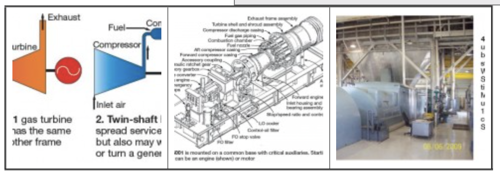
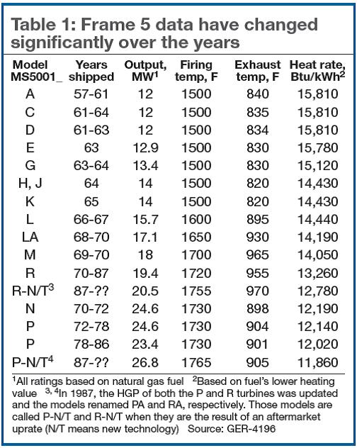
If the energy industry has an iconic gas turbine (GT), the consensus view probably would be GE Power & Water’s durable Frame 5. It certainly has stood the test of time: The first unit in this model series shipped from the OEM’s Schenectady factory 55 years ago and Frame 5s are still being built today—albeit by manufacturing associates abroad and at ratings about two and a half times those of the early engines (Tables 1 and 2).
In between, well over 3000 of these machines were assembled and shipped in both single- and two-shaft versions for electric-generation (50 and 60 Hz) and mechanical-drive applications (Figs 1, 2; Sidebar 1). Units in generation service are found in simple-cycle, cogeneration, and combined-cycle facilities (Fig 3). They are installed both onshore and offshore (oil rigs, barges) and may be equipped for single- or dual-fuel firing.
 A generation of GE gas-turbine designers and field engineers cut their proverbial teeth on the Frame 5. One of them, Dave Lucier, went on to instruct field service personnel and later manage GE’s field engineering program. Just prior to the millennium, he founded PAL Turbine Services LLC to solve problems owner/operators were having with legacy engines and controls, conduct inspections, and manage outages. Lucier has a deep appreciation for things mechanical and electrical, and believes a well-engineered product properly cared for should, in most cases, last as long as the owner has an application.
The Frame 5 is one of his favorite engines, Lucier admitted in a sit-down with the CCJ editors. It’s reliable and relatively easy to operate, maintain, and overhaul, he said. The historian in Lucier took over at this point: “You know, of course, that it was a black-start Frame 5 in Southampton, NY, that initiated the restoration of power on Long Island, and eventually New York City, following The Great Northeast Blackout, Nov 9, 1965. The future is nothing without the past,” he reminded.
The blackout made utility executives, particularly those east of the Mississippi, realize their systems were at risk without peaking units and black-start engines. Gas-turbine OEMs were inundated with orders. Frame 5 sales remained brisk until the oil embargo of 1973 took its toll on purchases. Note that a large percentage of the early “Fives” were designed to burn oil only; virtually all of the other units in electric-generation service were equipped to fire oil and/or gas.
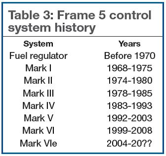
Reminiscing, Lucier spoke of the frenetic pace of GT activity in the late 1960s and early 1970s, which included his assignment to an installation and startup team for three four-unit power blocs—12 Frame 5s designed to burn oil or gas—at one Midwest utility. He also recalled being trained to provide support for engines that relied on Young & Franklin’s fuel regulator, as well as those with the first electronic system—GE’s Speedtronic™ Mark I—which superseded Y&F’s product on the MS5001N (Table 3). “There are still many units operating today with these early control systems,” he said.
A Frame 5 was incorporated into a combined cycle before the 1970s, Lucier mentioned while looking through a pile of reference material on his desk. And it’s still operating at Wolverine Power Supply Cooperative Inc, Cadillac, Mich (Fig 4). The 21-MW STAG 105 (1 x 1, single shaft) is one of two such combined cycles in the US with more than 40 years of service. The other is owned and operated by Clarksdale (Miss) Public Utilities Commission.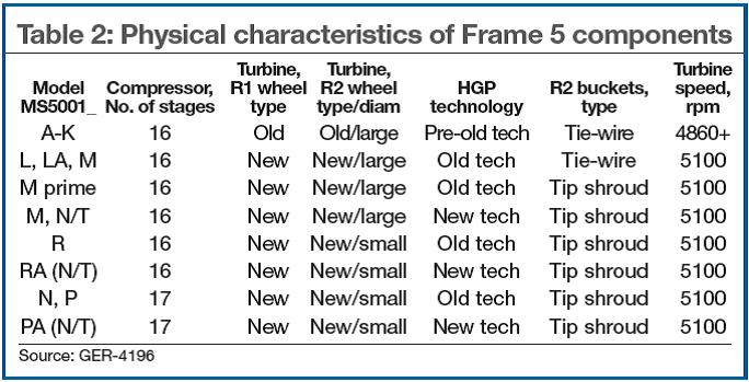
Frame 5s continue to serve their owners well—even engines dating back to the early 1960s. And in view of the high value placed on GTs that can “fill in” for intermittent renewables and provide other ancillary services, the operating lives of many engines are being extended. With a nominal 8- to 10-min start, Frame 5s satisfy the fast-start requirement grid organizations demand, with time to spare in some cases. Although rated capacities and efficiencies of the early units, in particular, are relatively low by today’s standards, a paid-for asset capable of operating on low-cost gas and/or No. 2 (distillate) fuel oil for a few hours when required has a place in the generation mix.
As the value of Frame 5s increases in many locations, investments to assure high availability and starting reliability—and possibly to reduce emissions—may be prudent. Controls upgrades usually get top priority based on an informal industry survey. Investments in efficiency improvements take longest to recoup, in most cases.
Experts suggest a thorough inspection of any engine being considered for upgrade before signing a contract. In some cases, the wear and tear of three decades or more of service, or simply standby duty in an engine-aggressive ambient environment, may point to the scrap heap because of the high cost of repairs or upgrades.
 You are unlikely to learn enough about a given machine’s condition to support an upgrade investment without removing the upper casing and lifting the rotor for a close-up inspection by one or more qualified experts. This can be done cost-effectively onsite by many third-party firms with access to the skills of retired GE field engineers. Due diligence is highly encouraged.
If the service life of your machine is approaching 200,000 factored operating hours or 5000 factored starts, a complete teardown of the turbine section is recommended by the OEM for safety reasons. If that inspection indicates the rotor and its component parts meet GE’s standards for continued service they can be certified for another 50,000 hours or more of operation and returned to service.
Third-party services firms also are competing for your business in these so-called end-of-life (EOL) evaluations. Research will point to some firms at least as qualified as the OEM in terms of personnel, tooling, expertise in nondestructive examination (NDE), etc. The advantages of qualified third-parties normally are very competitive pricing and fast turnarounds. As Lucier preaches: Knowledge + Experience = Savvy.
But they are not your only considerations. If you’re leaning toward a third party for an EOL exam, be sure to consult with your insurance carrier. A non-OEM probably would not assume the risks associated with “certifying” your rotor for “x” more hours and “y” more starts—if that’s what you’re looking for. However, they can offer a clean bill of health (if that’s the case) and suggest that the rotor should continue to operate reliably for a given period based on inspection findings and industry experience.
There’s also a “what if” to factor into your evaluation. What if your third-party services team identifies a defective rotor component—a wheel for example—what do you do? If you want to buy a new wheel, or more probably a refurbished one, where will you get it? Don’t expect the OEM to be compassionate. The bottom line: If you opt for a third-party EOL inspection, be sure the company you select has access to qualified rotor parts at pre-negotiated prices.
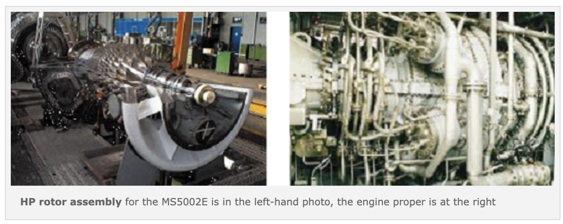
Sidebar 1. Two-shaft Frame 5s drive compressors, pumps, generatorsMost CCJ subscribers earn their living generating electricity and are very familiar with the MS5001—the single-shaft version of the Frame 5, which accounts for about 85% of the “Fives” built. The two-shaft engine, introduced in the 1970s, was designed specifically for mechanical-drive applications—typically to turn large pipeline compressors and pumps. Occasionally it is selected for electric generation service. You can find five models of the MS5002 operating worldwide today: A, B, C, D, and E. All can be equipped to burn a wide variety of gaseous and liquid fuels. The simple and robust designs of these engines are conducive to maintenance onsite without specialized tooling or service-shop assistance. The first two-shaft models, the MS5002A (19.6 MW/26,250 hp) and B (26.1 MW/35,000 hp) were developed simultaneously and based on the MS5001M and N compressor designs. In 1987, the MS5002B was upgraded using advanced materials and design features to resist high-temperature damage and wear and released to the market as the MS5002C (28.3 MW/38,000 hp). The A’s 15-stage compressor developed a pressure ratio of 7.4:1; firing temperature 1690F, heat rate 9780 Btu/hp-h. Compressors for the Bs and Cs each are 16-stage with a pressure ratio of 8.8:1; firing temperatures are 1700F and 1770F/heat rates 8830 and 8700, respectively. The D involved a more comprehensive upgrade than the C to develop its 32 MW/43,000 hp. The machine’s most significant feature is the replacement of the 16-stage B/C compressor with a 17-stage version (10.75:1 pressure ratio) derived from the MS6001B design, which many readers are familiar with because of the CCJ’s coverage of the Frame 6 Users Group. Extracting more power from the D also required use of a new first-stage nozzle design having a smaller throat area to fully exploit the high pressure ratio of the new compressor, while limiting firing temperature to 1807F to assure high reliability of hot-section parts. Advanced seals for the HP packing, No. 2 bearing, and second-stage shrouds blocks contribute to the performance improvement. The OEM offers a menu of upgrade options to improve the performance of the early machines—converting an A or B to a C, for example. A DLN retrofit may be required in cases where the basic engine upgrade requires the combustion of more fuel. If a DLN is in your future, the Mark II control system typically included with the As and Bs would have to be replaced with a Mark VI or VIe—or equivalent. The A-D two-shaft Frame 5s each have single-stage turbine drivers on their respective HP and LP shafts. The first powers the compressor, the second the driven equipment. Design of the MS5002E, rated 32 MW with a simple-cycle efficiency of 36% in mechanical-drive service/35% in power-generation service, is dramatically different than the earlier “Fives.” Key features of this engine are listed below. • Compressor: Scaled up directly from the GE10 gas turbine with more than 100 units installed worldwide; 11 stages; 17:1 pressure ratio; IGVs and first- and second-stage stator blades are hydraulically actuated variable vanes; fourth-stage bleed for LP turbine wheel cooling; seventh-stage bleed for cooling and for surge control during startup/shutdown; compressor rotor has a forward stub shaft, six discs, five spacers, and aft stub shaft restrained in compression by 26 tie bolts. • Compressor casing: Horizontally split; air-inlet casing supports No. 1 bearing, a combined tilting-pad journal and thrust bearing; inlet case is cast iron, intermediate case nodular cast iron, compressor discharge case (CDC) cast steel. • Combustion system: DLN2-class system installed on hundreds of gas turbines worldwide; six cans mounted on the CDC, each with five fuel nozzles; combustor operates in premixed mode above about 50% of the engine’s rated output and is capable of 25 ppm NOx on gas. • HP turbine: Two-stage reaction-type machine copied from the proven MS5002D; both stages of HPT buckets and nozzles are cooled by compressor discharge air. • LP turbine: Same design as that used on the LM2500+ aero with flow-path profile and airfoils redesigned to accommodate the higher air flow required by the MS5002E. • Controls: Speedtronic Mark VI. • Maintainability: Horizontally split casings and removable enclosure roof; power turbine mounted on a special frame that permits axial movement on the base plate; combustors can be disassembled without removing the CDC; bearing Nos. 1, 3, and 4 are easily accessed for inspection; internal crane provided for lifting of main auxiliaries; instrumentation racks are outside the enclosure to facilitate inspection and repair. The first commercial MS5002E began operating at a fertilizer plant owned by Yara Sluiskil BV in Sluiskil, The Netherlands, Nov 5, 2007. Tests at full load in the premix mode conducted at the end of 2007 and beginning of 2008 confirmed that the unit surpassed the contractually guaranteed electrical by about 1 MW, with 3% less fuel consumption than specified. DLN emissions were 12 ppm during the tests. The Yara engine operates on two fuels with different compositions and demonstrated its ability to adapt to any changes or blends in gas composition with no interruption in production.
HP rotor assembly for the MS5002E is in the left-hand photo, the engine proper is at the right |
Feeling comfortable now that your engine has a clean bill of health and your economic analysis indicates a certain upgrade makes perfect sense? If so, it could be your naivete showing. Have you considered what EPA might think about your plans? How much do you know about the federal agency’s alphabet soup of regulations—including National Ambient Air Quality Standards (NAAQS), New Source Review (NSR), New Source Performance Standards (NSPS), Prevention of Significant Deterioration (PSD), Best Available Control Technology (BACT), Reasonably Available Control Technology (RACT), Reasonably Available Control Measures (RACM), Lowest Achievable Emission Rate (LAER), etc?
This is where the realistic plant manager punts to the company’s environmental team. Let it carry the ball from here. Implement your engine improvement plan, or a modified one, only after receiving corporate approval. Environmental regulations are extremely complicated, and ambiguous by design some people believe, to give government the upper hand in legal challenges to any of EPA’s decisions. Plus, rules are constantly being changed by court cases: What was acceptable yesterday, might not be tomorrow.
Generally speaking, if your calculations show planned work (not just upgrades) will not increase emissions you should be fine. But be prepared that EPA might not agree with your calculational procedure, for whatever reason. The agency also may find that the new control system you want to install could enable the engine to operate in a manner that would increase emissions—even though you would not operate that way—and deny a permit.
Just when you’re getting used to having the environmental cards stacked against you, there’s yet another joker in the deck: An NSR trigger means greenhouse gases (GHG) must also be considered in the environmental impact analysis. Talk about a moving target, what’s today’s BACT for GHG? Tomorrow’s?
Frame 5 major surprise
Lucier, off the line after helping walk someone through a knotty combustor problem, returned to his history lesson for the editors, all 20 chapters of which can be read at his website (Black Start: The 1965 Blackout and the Power Generation Industry). An important part of GT history not included in his musings is the transformation in the dissemination of information enabled by the web and the positive impact it has had on owner/operators.
Lucier conducted his entire call via webcam, having the ability to see exactly what problem the mechanic had to deal with and to provide a solution—on the spot. Only a few years ago, this half hour of technology transfer likely would have involved hours of travel time. For a man already at the biblical three score and ten, minimizing the number of nights on the road is particularly important. Much more therapeutic is an evening drive in his Triumph TR6 in the Adirondacks, near Lucier’s Lake Placid (NY) home.
GE installed the first of its so-called packaged powerplants for South Carolina Electric & Gas Co in 1961, according to Lucier’s history book. The MS5001D was used primarily for peaking and emergency service. “The “packaged” concept was unique at the time,” the historian said, “with most of the primary and auxiliary components located on the same 36-in. I-beam base, together with the engine, during factory assembly.”
The “package” concept facilitated factory testing, shipment to the plant site via rail car or truck, and field installation. GTs for these plants were built in Schenectady and tested there at full speed/no load (FSNL) on liquid fuel. The speed reduction gear and generator were built in the company’s Lynn (Mass) works. Mechanical coupling and alignment of the principal components were done in the field. Control cabs, built in Salem, Va, also were connected onsite.
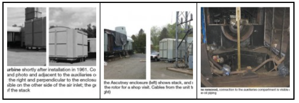
Sister units to the South Carolina engine were installed by Central Vermont Public Service Corp (CVPS) in Ascutney in 1961 (Fig 5) and in Rutland in 1963. Interestingly, these GTs are only a couple of hours by car from the offices of PAL Turbine Services and Lucier’s team has worked at both locations over the years.
Serendipity. A month after sitting down with Lucier, personnel from Genex Turbine Technologies, Manchester, Conn, told the editors at a meeting of the Combustion Turbine Operations Technical Forum that CVPS had hired Genex to overhaul its Ascutney unit. Already planning this report, the editors were invited by CVPS to Ascutney for a first-hand look at the work being conducted (Figs 6, 7). Oil-only Ascutney and its sister unit at Rutland provide non-spinning-reserve fast-start (10-min) capacity and black-start services to the grid.
Johnson described the Rutland GT as being in “pretty fair shape.” First-stage buckets and vanes were “rough,” tip rubs were in evidence, bearings needed work. PAL provided a technical advisor for engine disassembly, which was done by utility personnel. Shop work was contracted to Dresser-Rand Turbine Technology Services (Leading Edge Turbine Technologies Inc at the time of the Rutland overhaul).Mechanical Engineer Randy Johnson managed the major inspection for the utility. CVPS hired a turbine services firm for disassembly and reassembly and contracted with Genex for refurbishment of all stationary components and bucket repairs. Rotor and casing work was subcontracted by Genex to Elliott Turbomachinery Group’s Pittsburgh Service Center. Johnson’s goal was to apply lessons learned from previous majors to the Ascutney project (Sidebar 2). Most recent experience was the Rutland Frame 5’s second major in 2009. The first was in 1986.
Sidebar 2. Backgrounder on CVPS Frame 5sHydro aside, half a century is a long time for any generation asset to operate productively. Central Vermont Public Service Co’s Rutland and repowered Ascutney MS5001D peakers hit the Big Five-O next year for a couple of reasons: (1) They are meeting grid expectations for the capacity and black-start services provided under contract, (2) The utility has invested, as necessary, for repairs and upgrades to keep the engines competitive. Here’s a snapshot of a few entries from the log books for these units: • Control systems for Ascutney and Rutland were replaced by Innovative Control Systems Inc in 2005 and 2006, respectively, to assure continued high reliability. The company had provided hundreds of PLC-based controls solutions before it was purchased by Emerson Process Management’s Power & Water Solutions unit a couple of years ago. • Ascutney’s exhaust silencers and stack were replaced several years ago with upgraded stainless-steel components. • Both Ascutney and Rutland operate on low-sulfur distillate oil today. Rutland burned Bunker C for several years after commercial start. The auxiliary skids for both machines have been upgraded over the years. Flow dividers are of the free-flow type—that is, fuel flow creates the turning power. Model 903 Cummins diesels, which replaced the original VT8-430 Cummins recips in the 1980s, crank the units. Both GTs can be started remotely (units are unmanned) and have ratchet-type turning gears. An operator is dispatched after a unit is started. • As for problems, Rutland had fuel-nozzle issues—specifically coking after restart. Replacing the nozzles solved the problem, so a root-cause analysis was not pursued. The utility has not had the opportunity for a long run on the unit since the 2009 major inspection. One reason: Fuel oil is expensive and kilowatt-hour sales would not be profitable. • Rutland had vibration issues, so the rotor was disassembled and rebalanced. One cause of vibration, blade migration, was corrected by skim-cutting the locking wedges for each stage. |
A lesson learned that was applied to the Ascutney major: Use outside labor for engine disassembly and reassembly. Utility mechanics had a heavy work load at the time of this project and there was thought to be a schedule advantage in using outside labor more familiar with GTs than the hydro-oriented CVPS mechanics. The lesson learned at Ascutney is that MS5001Ds are much different than the latest “Fives” and it is difficult to bring together an experienced team for this particular model. Johnson said someone told him that of the 30 MS5001D engines produced only four remain in service—including the two at CVPS.
Rated 13.3 MW when originally installed, Ascutney had roughly 14,000 factored hours and 5000 factored starts when the decision was made to conduct the major in June 2011. To maintain the degree of operational readiness required by its grid contract, Ascutney had been conducting two test runs a month for several years—one FSNL, the other loaded. In a typical year the unit might be called on to run about a half dozen times and deliver power for six to eight hours after each start. The limited run time causes significant wear and tear on the turbine wheels. Plus, the high-moisture environment of lush southern Vermont is conducive to corrosion.
So it was not a complete surprise when CVPS got the word from Genex that the buckets for both turbine stages (the Frame 5 has only two turbine stages) were frozen into their respective wheels (Sidebar 3). In addition, both stages revealed tip damage from casing rubs and the angel wings exhibited wear from mild rubbing. To illustrate how “frozen” the buckets were in the wheels, it took about 12 hours to remove three first-stage airfoils. A simple visual examination showed the R1 fir trees were no longer fit for duty (Figs 8-10).
Note that the assembled rotor (compressor section, distance piece, and turbine section) had been removed from the package and trucked from Vermont to Pittsburgh. The original generator and exciter remained in place, properly heated for protection against moisture ingress. The generator had never been disassembled although it had been inspected and cleaned, with no issues identified.
The preferred option would have been to replace the Ascutney first-stage wheel and perform the EOL inspection as suggested by the OEM, because the unit had reached 5000 starts. But a replacement wheel could not be located. Johnson thought the second-stage wheel could have been salvaged and the tip rubs trued-up, but that became a moot point. Meanwhile, destacking of the compressor section hit a snag when those wheels got hung up on the through-bolts because of severe corrosion.
Ageing assets can present unforeseen problems. By contrast, the major on Rutland, about an hour drive from Ascutney, two years earlier went smoothly. No one expected the Ascutney rotor to be in such poor condition. There also was some casing damage requiring repair.
What to do? Good luck and a little help from your friends count when “smarts” aren’t enough. Team Genex was hot on the trail of an MS5001D when the editors phoned during a trip south early this year to inspect a unit installed in 1963 and retired in 2007 with 7566 fired hours and 1866 starts. After reviewing the results of a borescope inspection report and making an external inspection of physical condition, Genex gave the machine two thumbs-up and bought it. The entire unit from the compressor inlet to the generator coupling, casings included, was loaded onto a truck and shipped north.
Genex’s subcontractor broke the casing, losing only at most 10% of the bolts, and found the flanges in relatively good condition. The unit was cleaned and inspected, and critical measurements confirmed (Figs 11, 12). However, the as-received rotor had a degree of imbalance and balance-weight locations did not follow normal industry convention. Logic suggested breaking the marriage coupling and balancing each of the rotor components separately.
However, as the saying goes, no good deed goes unpunished. Three marriage bolts sheared off during the unbolting process and extraction of the segments would have been especially difficult (Figs 13, 14). So the 16th compressor stage from the original Ascutney rotor was removed swapped-out with that on the replacement rotor. A new set of matched marriage bolts was required, but the compressor through-bolts were salvaged.
Best practice for marriage-joint repairs on this machine, according to shop personnel, was to skim-cut or grind to correct axial and radial runouts, then do a light grind on the dummy journal (on the 16th stage under the marriage joint) to be sure it’s “true.” Finally, use balance weights to meet runout specs.
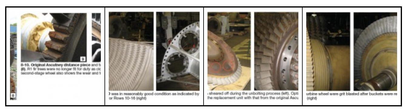
With the buckets out of the wheel, fir trees were grit blasted and inspected; no cracks were found. The second-stage turbine section, including blades, was cleaned up as-received (Figs 15, 16). The work scope was designed to accommodate the planned operating regimen (a nominal 30 annual starts and 60 run hours) at optimal cost; there would have been no commercial advantage gained by removing the R2 buckets and cleaning the fir trees as was done for R1.On the turbine end, the first-stage buckets were removed and sent to Genex for reconditioning, including repair of angel wings. Genex also repaired other hot-section parts—including liners, cans, transition pieces, first- and second-stage nozzles, second-stage diaphragms, etc.
The rabbet-fit area and faces were dressed while light machining maintained concentricity at the marriage joint to assure a proper interference fit with liquid nitrogen used to shrink the turbine end. After the reconditioned R1 buckets were installed in the wheel with new seal pins and rock was verified within OEM specs, the turbine was balanced at low speed. The turbine and compressor sections then were rejoined and, after checking runout, the complete rotor was balanced at low speed.
Turbine nozzles were in reasonably good condition; only a grit blast was necessary. Shroud blocks were removed and inspected for cracking. The blocks on the replacement engine were in much better shape than the original Ascutney machine (Fig 17). After cleaning up some dents and dings, shroud blocks were cleared for duty. The ninth-stage hook-fit area, which is prone to cracking as Frame 5s age, was in good condition (Fig 18).
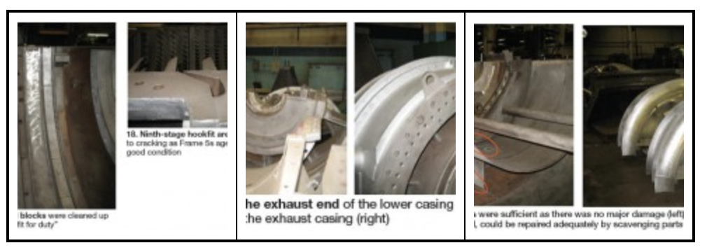
General condition of the exhaust end of the unit was fair (Figs 19, 20). Several small patchwork-type repairs were required on the exhaust housing, as one would likely expect (Fig 21). A segment of the exhaust diffuser was damaged and it was repaired with a section from the original turbine (Fig 22). Journal and thrust bearings were rebabbitted and seals replaced. Shaft journals just required polishing.
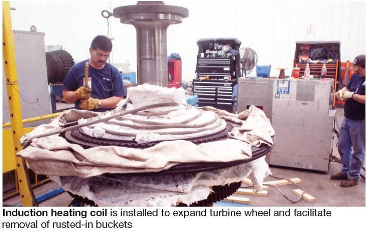
Sidebar 3. How to remove buckets rusted into turbine discsMaterials of construction, ambient environment, and operating regimen sometimes combine to create a cementitious rust that locks buckets into turbine discs. Removal, as experienced during the Ascutney overhaul, can be virtually impossible. The firm servicing AECI’s Unionville Unit 2 rotor experienced a similar difficulty when it was sent to the shop. The first thought was to slowly rotate the turbine rotor through a heated solution formulated to penetrate the rust between the bucket roots and wheel dovetails. This method didn’t meet expectations. Next, a specialty contractor tried its luck using induction heating to expand the disks and dry ice to shrink bucket roots (photo). Success! The buckets came out as if there was grease on them, one plant person said. Later, the rotor and buckets were grit-blasted. Minor tip rubs on the first-stage buckets and the few indications found on the rotor disks were blended out. On reassembly, machinists found that the fit between the blade roots and disc dovetails was within the OEM specification and no work was required. However, the locking device had excessive play. In effect, the turbine disc had “shrunk” because of material loss. A 30-mil coating was metal-sprayed on the disc, thereby enabling proper fit-up of the locking device without any machining.
|
Weak ankle
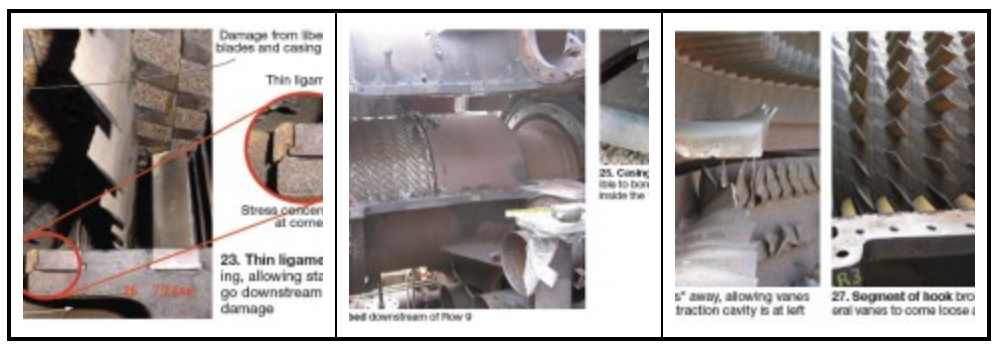
The Frame 5 is a beast. In horse terms it can be compared to a Clydesdale, but one with the ankle of a thoroughbred. The Five’s ankle is the thin ligament at the 10th stage extraction slot in the compressor section. It forms the hook that holds one side of the ninth-stage compressor stator vanes in place. Fig 23 shows the area of interest as well as the damage caused when the casing cracks, allowing the vane to work free and one or more airfoils to go downstream. Fig 24 illustrates the damage south of the ninth stage in greater detail.
Rodger Anderson, manager of GT technology, DRS Power Technology Inc, Schenectady, NY, and previously a lead design engineer for GE’s gas turbine division, has seen this type of failure in many Frame 5s over the years. He says it is the result of a gray cast iron casing weakened by (1) corrosion, (2) the uplift loading on the ligament area created by airflow through the compressor, and (3) the numerous start/stop cycles associated with peaking service. Recall that gray cast iron has poor tensile and fatigue properties.
The casing cracks before failure, Anderson continued, and the vane loading will propagate the crack. Thus regular checks of casing condition in the extraction cavity during borescope inspections can warn of impending failure (Fig 25) and enable corrective action before serious damage occurs—as shown in Figs 26 and 27.
Lift the upper half of the compressor casing about 2 ft above the horizontal joint and support it in that position. Option 1. The compressor expert offered three hook repair options for users to consider depending on the extent of cracking. Option 1 is an effective least-cost approach for cracks less than 6 in. long at either (or both) of the horizontal-joint locations. Here’s how Anderson approaches this repair:
• Inspect hook fits on both sides of the upper and lower halves of the casing at the 10th-stage extraction groove. If your inspection confirms borescope findings that any open crack is less than 6 in. long (Fig 28), remove stator vanes from the horizontal joint through two vanes beyond the end of the crack—as many as five airfoils in total.
• Drill the square bases of the vanes to accept the spring pins shown Fig 29 to create a rigid vane segment. This is the technique Anderson developed to prevent fretting wear caused by loose vanes in casing grooves. More than 120 turbines worldwide are running with over 80,000 pinned vanes. Fleet hours total more than 3 million; multiple fleet leaders have passed 50,000 hours. Reliability is 100%—meaning there have been no vane failures or shim liberations since the first vanes were pinned more than 10 years ago.
• Drill and tap a hole in the center of the back side of the platform for the vane at the horizontal-joint location and then drill a hole through the extraction-cavity wall to align with that hole (Fig 30). A bolt anchors the vane to the bottom of the casing groove (Fig 31). A retaining clip is installed as shown to hold in place the free end of the cracked hook fit. In cases where vanes on opposite sides of the horizontal joint are bolted in place, elongated holes in the casing are necessary to accommodate expansion.
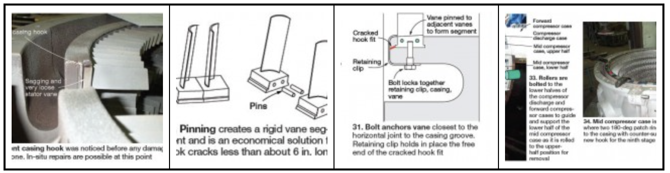
Option 3, the most extensive solution, is used when a 360-deg patch ring is required or desired. After the upper casing is removed in the manner described for Option 2, the lower casing half is removed by rolling it around to the upper-half position using the mobile crane (Fig 33). Both casing halves are bolted together in a capable shop and machined for a 360-deg patch ring (Fig 34). Back at the plant site, the lower casing half is rolled back into place and bolted to the forward and aft cases. Then the upper-half casing is lowered into place and bolted to complete the assembly. Option 2 is Anderson’s solution for a crack in the upper half of the casing that exceeds 6 in. in length. The upper casing half is removed using a mobile crane and shipped to a machine shop where a 180-deg patch ring is installed at the 10th-stage extraction groove. Of course, the enclosure roof and side panels, as well as some of the combustion hardware, must be removed to lift the upper casing. The patch ring is described in Fig 32.
Inspect regularly
It’s not difficult to convince yourself that a robust Frame 5 relegated to capacity, black-start, voltage support or other grid service—logging perhaps a dozen starts and 50 or so hours of run time annually—doesn’t need borescope inspections on a regular basis.
But that would be a mistake. Gabe Fleck, an electrical engineer with Associated Electric Power Cooperative Inc (AECI), Springfield, Mo, and the chairman of the 501D5/D5A Users, explained how periodic borescoping prevented catastrophic damage in one of his company’s legacy engines several years ago.
AECI installed in rural Missouri, in 1976, two oil-fired MS5001Ps equipped with Mark II control systems for the primary purpose of maintaining voltage stability in an area served by one transmission line. For 30 years following COD, the unmanned Unionville GT Power Plant averaged two fired starts per month and about 40 operating hours annually—primarily to confirm reliability. The units very rarely ran with the express purpose of supplying kilowatt-hours to the system. In fact, Fleck said he couldn’t remember one time in the last decade that they did.
The engines typically are inspected every two or three years, the gas-turbine expert continued. Several borescope inspection ports are provided on the Unionville Ps for this purpose—two on each side of the engine, one on each of the 10 combustion cans. Back in September 2005, Fleck went on, Florida-based Advanced Turbine Support LLC (ATS) checked the machines from the IGVs to the exhaust plenum.
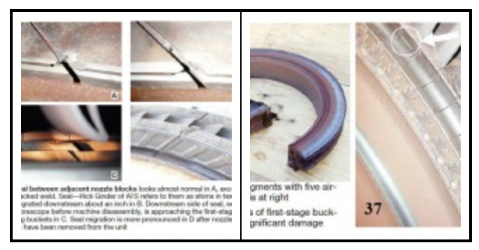
Borescoping of Unit 1 gave no reason for immediate concern but inspection of Unit 2 did. The most important of the technician’s findings was that spot welds retaining the inner seals provided between adjacent first-stage nozzle segments had cracked in two instances (Figs 35, 36).
This allowed those seals to migrate downstream into the space between the first-stage nozzles and buckets (rotating blades). Rubbing was observed on platforms of first-stage buckets, but there was no indication of significant damage (Fig 37). Note that when a weld breaks, the seal does not just come loose and travel downstream; the resistance fit restricts its movement to small increments over a period of time. The seals are about 7 in. long and slightly less than a quarter of an inch wide; the gap between nozzle and bucket is 0.345 in.
Initially, the customer and we thought that there wasn’t enough room for the shim to come out—that it would just continue to move back and forth in the seal slot. However, we learned over time that shim contact with the rotating buckets was actually pulling the shim out from between the nozzle segments. Upon confirming this, the unit was removed from service and repaired.”Vendor selection. Fleck stressed the importance of proper due diligence in the selection of a borescope inspection service. Another vendor might have missed the traveling seals, he said, but ATS knew exactly what to look for on these particular machines. “We started out monitoring a first-stage nozzle shim for a Florida utility,” the inspector recalled. “For two years we watched the shim move back and forth between the trailing edge of the first-stage nozzles and the leading edge of the first-stage buckets.
Based on this experience, ATS implemented an inspection program for all Frame 5s that requires the checking of each shim to see if it is moving and/or if the tack weld holding it in place is cracked. The company also inspects closely first-stage buckets for signs of rubbing.
Since finding the first migrating seal, ATS inspectors have identified loose seals on several more units. Still more might have been found if all customers had been diligent about removing all 10 fuel nozzles. Some choose to pull only two to four nozzles, despite knowing this type of damage might be overlooked.
The “traveling seal” problem dictated a shop visit for this rotor, where severe rusting made removal of buckets from the wheels particularly difficult. Fleck explained that the Unionville peakers operate in a high-humidity environment and that about half of their lifetime starts had been for reliability testing.
Company procedures called for a one-hour test, mindful of fuel cost, emissions concerns, cost of personnel to conduct the tests, etc. However, an hour was not sufficient to heat-soak turbine components and the resulting moisture took its toll over the years. New procedures call for cranking each engine once in the first and third calendar quarters, and starting each once in the second and fourth quarters and running for three hours each time.
Controls retrofits
Most Frame 5s earn their keep providing black-start, emergency capacity, peaking power, and other ancillary services. One look at the heat rates associated with the various models of the MS5001 (last column in Table 1), and the fact that many of these engines built before the mid-1970s are oil only, tells you most users are not competitively bidding kilowatt-hours.
In the market segments typically served, reliability is of greatest importance and controls upgrades are viewed positively—even by parsimonious owners. They know that once in a while you have to spend a buck to assure a revenue stream. Those users interested in performance upgrades are referred to GER-4196, “Performance and Reliability Improvements for MS5001 Gas Turbines” and similar documents, available on the Web. There are far too many performance-improvement opportunities offered by the OEM to do the subject justice here.
There’s usually good reason to consider a controls replacement on virtually any “Five” that is 30 or more years old (Fig 38). It can be tough getting parts/service for fuel regulator and Speedtronic I and II systems. When the financials support a controls upgrade for your units, there are two basic options: a PLC-based system or a DCS.
After speaking with several owners, the editors learned that with control-system cost pretty much a tossup among third-party suppliers, selection comes down to schedule, the capabilities of plant personnel, and spare parts. The supervisor of a municipal plant said his city’s power and water departments shared personnel and the water infrastructure was controlled by Rockwell Automation/Allen-Bradley PLCs. With a knowledgeable labor pool already available, a DCS didn’t get serious consideration.
Another owner with several generating plants controlled by Emerson Process Management’s Ovation™ said savings in spare parts, plus having experienced technicians available on-call to service the Frame 5 peakers, supported the decision for a DCS. Yet another user told the editors that opting for a DCS provided schedule benefits.
Patrick Nolan, Emerson’s director of gas-turbine solutions and an expert with 25 years of experience in managing businesses dedicated to engineering, installing, and commissioning both PLC- and DCS-based controls upgrade solutions, told the editors the two types of systems can be installed in about the same amount of time because as much as about 90% of each application is “standard.” The remaining 10% has to do with customer preferences.
Nolan said, “Users can ensure a successful controls retrofit with relatively little upfront work at the procurement stage. Specs are relatively standard from user to user and best achieve their goals by being functionally descriptive rather than hardware-centric.” To keep the project affordable, he recommended that users resist the temptation to specify a unique solution. He advised procuring such projects on a turnkey basis to hold down costs.
Some customers want to manage the installation activities themselves and have the control-system bidder only provide a technical advisor. Nolan advised owners to carefully consider the benefits of this, explaining that the lowest cost is achieved when the supplier is responsible for the entire package. Modernization of Frame 5 controls is a “very standard application,” for experienced vendors, he added.
The cost/benefit of additional upgrade enhancements is strongly influenced by the particular vintage and model of turbine. The controls expert encouraged users to address the main problem items—such as variable-displacement pumps for the fuel systems on old Frame 5s—and not to unduly drive up project costs with “nice to haves” that may not directly improve overall life-cycle costs.
PLC controls. Kentucky Utilities Co recently upgraded the controls on three 20.7-MW MS5001Ms installed in 1969-1970 at the Heafling Gas Turbine Plant in Versailles, Ky, near Lexington. Production Supervisor Greg Wilson told the editors that reliability concerns with these black-start peaking GTs, each having about 30,000 fired hours of service, motivated the controls upgrade.
Petrotech Inc, Houston, was the winner among several bidders, offering a PLC-based system with Allen Bradley components familiar to many utility personnel. An eight-week outage was needed to convert all three oil/gas-fired units from Speedtronic I to a system underpinned by programmable logic controllers. Local electrical contractors handled the field wiring and instrumentation under the supervision of a Petrotech technical adviser.
The primary goal of the project, said Petrotech’s Steve Cernik was to upgrade the turbine control systems to increase reliability and safety and to facilitate troubleshooting, maintenance, and normal operation. Wilson confirmed that the new control system has been in service for several months and is meeting expectations.
The Petrotech system controls starting, synchronization, operation, and shutdown. It enables the three GTs for full automatic black-start and non-black-start sequencing and control in both local and remote modes. Bumpless transfer between liquid and gas fuels also is assured. The control system also allows running on mixed fuel if desired.
Startup sequence for the new control system generally proceeds as follows:
• Shutdowns/relevant alarms clear, operation selector in appropriate position.
• Local/remote start command.
• Lube-oil pump, cranking motor/diesel start and unit accelerates to cranking speed.
• Ignition and flame detection.
• Warm-up complete, unit accelerates to 50% speed.
• Diesel engages, idles for five minutes and shuts down.
• Turbine accelerates to 100.3% speed.
• Synchronization is next—by manual means or by using the autosynchronizer to modulate turbine speed. Breaker closes.
• Load increases to pre-selected value if this feature is activated, or spinning reserve otherwise.
• If in isochronous mode, controller matches frequency set point.
• If in droop mode, controller matches a load set point—unless base, peak, or peak reserve is located. In this case, the controller will match the corresponding temperature or maximum-load set point.
In addition to the normal start sequence, a fast-start sequence shortens the amount of time required to get the units in service by reducing the warm up time and increasing the rate of acceleration.
DCS solution. The Piqua Municipal Power System, headed by hands-on Director Ed Krieger, provides electric service to more than 10,000 households and businesses in the Ohio city. Utility personnel take great pride in their system’s service record. In 2011, the overall average service availability index was 99.99%: The average Piqua electric customer experienced fewer than two outages of less than 33 minutes each.
Krieger knew the company’s enviable record was at risk given the age of the control systems married to its two simple-cycle gas turbines; nuisance shutdowns had become problematic. Piqua is a member of American Municipal Power Inc (AMP), a nonprofit corporation that owns and operates power generation and delivery facilities to provide its 129 member companies reliable, competitively priced electricity. The city also participates in the PJM Interconnection LLC’s demand response program, so its generating units must start when required to avoid financial penalties.
The kilowatt-hours provided to Piqua’s customers are produced by several projects the city holds minority interests in through its AMP membership—including renewables. Primary purpose of the two oil-only legacy gas turbines—a 21-MW MS5001N (Unit 8) and a 15-MW W191G (Unit 9)—is system reliability. They are black-start capable and can support critical loads in the city if the grid fails and Piqua disconnects to run in island mode.
Years back, the city generated its own power, but that stopped in the 1990s when its 60-MW coal-fired unit was shut down. The Frame 5 was purchased new in 1971; the 1960s-vintage W191 was pre-owned and relocated to Piqua in the late 1980s.
The city engaged Kansas City-based Sega Inc in spring 2011 to provide guidance in drawing up bid documents with detailed specifications for a new Frame 5 control system. Emerson Process Management Power & Water Solutions was awarded the competitively bid project. But before the project could get underway, the thin ligament at the 10th stage extraction slot cracked during a normal unit shutdown, releasing ninth-stage stator vanes and destroying the back end of the compressor (refer back to the section, “Weak ankle”).
A major overhaul was initiated promptly, with Sulzer Turbo Services hired to repair the rotor. The company got high marks for its work on the project from Krieger. One of the enhancements Piqua selected was coating of the new compressor blades to protect against corrosion pitting during the long periods the machine sits exposed to a humid ambient environment. The exhaust diffuser and flex seals also were replaced at this time with stainless steel components from Braden Manufacturing LLC; installation was done by ProEnergy Services.
In parallel with the major overhaul work, Emerson replaced the Frame 5’s Mark I turbine and generator controls with an Ovation turbine control system. Krieger commented that the Frame 5 was an easy machine to upgrade. A small crane was used to pull the Mark I package (Fig 38) from its housing and the Ovation cabinet was skidded right into the space vacated (Fig 39).
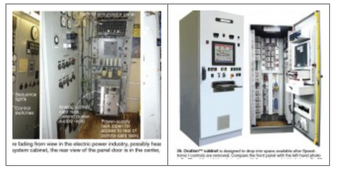
Remote control capability.The Ovation system—including controller, I/O modules, power supplies, touchscreen interface, and turbine-control application software—was pretested in Emerson’s shop before being shipped to the site. It monitors about 200 I/O points for the Frame 5. Krieger said that Emerson recommended several “no-brainer” enhancements that were implemented, including the following:
• Modern screens that enable operators to know why the unit trips if it does.
• Fuel oil system upgrade, including a new fuel valve with upstream/downstream pressure transmitters.
• Excitation system upgrade.
• Power monitoring through a protective relay with Modbus serial communication.
• Rewiring of the turbine base.
• New thermocouples.
• Flame detection system upgrade.
• Compressor-discharge pressure transmitter.
Asked what he thought of the new system, Krieger said simply, “When we call for a start, it runs.”
Fuel system upgrade
Ageing fuel control systems, like the ageing turbine control systems discussed in the previous section, often have a negative impact on engine reliability. Sometimes only after upgrading to today’s technology can you appreciate the advancements made since your Frame 5 entered service. A case in point is two gas-fired MS5001 machines that generally have operated base-load since entering service in 1967.
The owner, who asked not to be identified, had upgraded the engines’ control systems to Emerson Process Management’s Ovation™ before tackling the fuel systems earlier this year. Both upgrades have met expectations. The user’s comment after the fuel system was modernized: “It was a simple ‘push button and watch’ startup—the first of its kind here in many years.”
The original fuel control system, supplied by the OEM, was standard for the day (Fig 40). The equipment replaced and upgraded was provided to GE by Young & Franklin Inc and Fisher Governor Co. Today the latter, known simply as Fisher®, is a subsidiary of Emerson. Issues affecting the original equipment included the following:
• Contamination of instrument air, which interfered with position tracking by the Fisher pneumatically actuated pressure control valve.
• Normal wear and tear of the actuator for the Y&F Series 6000 combined control and stop valve contributed to hysteresis, which was not easily corrected because of poor support for low-pressure mechanical servo valves. Note that the Y&F valve is controlled hydraulically from the 40-200-psig control oil system via an I/H (electric current to hydraulic pressure) converter.
• Varnish in the hydraulic oil system, which caused unit trips and failed starts.
• Wear of the I/H converter supplied by Tri-Sen Systems Corp, for which there was little-to-no support. Failure of the I/H converter to operate as expected directly affected engine starting and operational reliability.
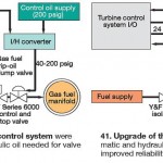
Replacement of the hydraulically and pneumatically actuated valves with Y&F’s electrically actuated alternative simplified the fuel control system and eliminated the least-reliable devices—specifically, the solenoid trip-oil dump valve and I/H converter (Fig 41). Prior to conversion, servicing of the fuel control system was required annually; calibration and cleaning of the instrument-air controller and I/H converter was necessary triennially. The mean time between service calls for the new system is projected at 10 to 20 years with no calibration of the isolation valves or gas control valve required.
End-of-life inspection
OEMs tell users gas turbines have critical parts with finite lifetimes and that replacement of these parts may be necessary to assure reliability and safety moving forward. Rotors are a primary target of this initiative. Their lifetimes depend significantly on service history. Today, the only way to reliably determine if an ageing rotor is in sufficiently good condition to continue operating is to disassemble it and to nondestructively examine individual wheels, bolts, etc.
GE’s Technical Information Letter (TIL) 1576, issued in 2007, requires rotors with 200,000 equivalent operating hours or 5000 equivalent starts (whichever comes first) to undergo a comprehensive inspection. Hours-limited rotors that pass inspection, with or without rehabilitation or replacement of critical parts, can be certified for extended service (50,000 or more hours). The OEM’s current position reportedly is that rotors having accumulated 5000 starts are at end of life no matter how good they might look.
Generally speaking, Frame 5s owned by electric utilities and independent power producers probably would bump up against the starts limit first because of their widespread use in peaking service. Those used in cogeneration service at refineries, chemical, and other process plants likely would be hours-based engines, as would “Fives” driving gas pipeline compressors.
According to GE presenters at user-group meetings, rotor life limiters fall into two categories:
• Low-cycle fatigue (LCF) cracking/fracture, and
• Creep rupture.
The first is the result of service-induced accumulated cycling and usually identified in areas of stress concentration and at locations of (1) initially acceptable forging inclusions or (2) inclusions that could not identified using the nondestructive examination (NDE) tools available when the rotor was manufactured. Note that operation at low ambient temperatures and age-related embrittlement of the rotor material can reduce fracture toughness.
Creep rupture is a time-dependent life limiter influenced significantly by temperature and stress. This is why it’s particularly important to maintain wheel-space temperatures within OEM guidelines. Crack growth can be time- or cycles-dependent, thereby creating the potential for crack propagation to be a mixed-mode life limiter.
OEMs and NDE. When it comes to discussion of NDE tools for deciding whether your rotor gets a “thumbs up” or “thumbs down,” the OEMs offer much less detail in public forums than third-party service providers. Perhaps the latter must dig deeper to provide owners the level of detail they and their insurers need to decide on retirement or continued operation. When OEMs conduct inspections their decisions on rotor life, in effect, are “rule of law.” What owner or insurer is going to question the OEM’s view?
To illustrate the level of detail an OEM offers on its rotor life inspection process, consider the following publicly available information:
• Visual inspections.
• Dimensional inspections.
• Magnetic/fluorescent particle inspection.
• Eddy current inspection.
• Ultrasonic testing.
A third-party view on GT end-of-life (EOL) inspections was provided by Paul Tucker of First Independent Rotor Service of Texas (FIRST), Humble, Tex, and Gary Hensley of Veracity Technology Solutions, Tulsa. Tucker and Hensley were two of the principals in the first third-party consortium to conduct EOL inspections of GE frames following the release of TIL 1576. Some believe Tucker, who worked in GE rotor shops for more than two decades before striking out on his own, and Hensley, who previously was responsible for the development of NDE tools for Siemens, may have done their first Frame 7 EOL inspection before the OEM did one.
The results of that work were reported at the CTOTF Fall Turbine Forum in 2007. The 7C rotor inspected came from a 1 x 1 STAG 107 combined cycle installed at Arizona Public Service Co’s West Phoenix Generating Station in 1976. It had more than 6000 actual starts at the time of the inspection and is still in service today.
The rigorous EOL inspection program—including visual, magnetic-particle, ultrasonic, and eddy-current NDE, as well as metallurgical and dimensional verification—revealed no reportable indications. This led the inspection team to conclude, based on inspection-process fidelity, inspection methodology/criteria experience, and the excellent inspection report, “that it is more than reasonable to assume no defects would grow and propagate into anything near critical flaw size in the next major inspection interval.”
Tucker and Hensley discussed with the editors ongoing work in EOL inspections, which at the moment, focuses on several Frame 5s. Inspections conducted to determine if an engine is fit for duty include the following:
• 100% three-dimensional boresonic inspection for internal flaws.
• Eddy-current inspection for creep.
• Hardness and replication for grain structure.
• Critical diameters measured for bore shrinkage.
• Finite element analysis (FEA) when flaws are identified.
Regarding the last point, FIRST and associates have developed rotor-component fracture models to perform FEAs when needed. Tucker said that FIRST’s critical flaw-size and fatigue- life estimations enable the company to analyze flaws with its models to see if flaw characteristics are detrimental to machine operation. He said the models can determine if specific flaws will fail, and if so, when in terms of hours and/or starts.
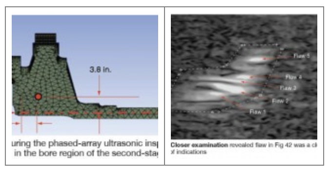
For Frame 5P EOL inspections currently being conducted in FIRST’s shop, technicians are checking compressor wheels for Rows 13 to 16, the distance piece, and both the HP and LP turbine disks. In one of the machines, a phased-array ultrasonic inspection revealed a flaw in the bore region of the second-stage turbine wheel (Fig 42). Closer examination revealed five significant indications in a cluster formation (Fig 43). Two of the indications (Flaws 1 and 2) were of significant concern because of sharp projections emanating from their blunted ends.
A more exacting analysis would have been possible if FIRST had information pertaining to the residual–stress state inherent in the disc as a result of the hot-spin process performed during its manufacture. Note that a hot spin reduces the wheel’s operational tensile stress by locking in a compressive residual stress in the bore region. Absent that, and stress-strain data to accurately reflect the plastic behavior of the disc material, the company recommended that the disc be removed from service.A detailed FEA showed the flaw was located in a region of high shear stress at a significant stress gradient and that the region of concern was above the material’s yield strength, based on the information available to the inspection and analysis team.
Not all flaws are show-stoppers, however. For example, a flaw was found in the 16th-stage compressor wheel of a rotor with 4800 starts. FEA showed it to be “non-detrimental.” Tucker said that the material used for compressor wheels is more forgiving than that used in the manufacture of turbine discs. At this point he stressed, “What you might find is not always bad,” mentioning that some users he speaks to believe a material defect means the part must be scrapped. Not true, Tucker continued, it’s not a “gloom-and-doom” thing.
Inspections conducted by FIRST and its alliance partners nominally take five days, a fraction of the time typically quoted by the OEM. However, analysis of any flaw that might be found can add a couple of weeks or more to the schedule. Tucker suggested that owner/operators do an EOL inspection earlier rather than later—during a major or when you’re going to replace compressor blades.
Having a baseline condition assessment enables users to better manage the lives of their rotors. Plus, if it appears that one or more components will have to be replaced in the future, knowing earlier allows owner/operators to plan for that eventuality and to order refurbished or new parts on a standard delivery schedule.
Tucker mentioned ongoing work by aimed at developing a new protocol to enable specific rotor-in-place tests for EOL evaluations. If that work is successful it would eliminate the need for unstacking the rotor in a shop unless a flaw is found or other work is required.
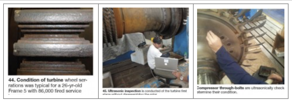
Some preliminary work in this area was described to the editors by Veracity President Kevin McKinley. He said Veracity was tasked to develop a set of inspections for a Frame 5P (86,000 fired hours; COD 1986), that together with metallurgical data, would enable its owner to have an accurate condition assessment without disassembly. The three inspections listed below were specifically requested by the user.
• Advanced Impedance Plane Analysis eddy-current inspection of R1 and R2 turbine fir trees to look for evidence of creep cracking, as well as other material deficiencies related to unit operation (Fig 44).
• Single-element and linear-array ultrasonic inspection of accessible areas of the R1 and R2, including fir trees (Fig 45). Additional 3-D modeling of the volumetric inspections was conducted to increase the probability of detecting any subsurface anomalies.
• Ultrasonic inspection of through bolts (Fig 46).
Veracity recommended additional inspections—such as 100% eddy-current inspection of all rotating and stationary compressor airfoils—but the user opted instead for penetrant inspections of compressor blades done by plant personnel. CCJ