

CONTENTS: Coverage includes best practices, Individual Achievement Awards, hot walkdown and offline inspections, water chemistry, BOP.
Beyond gas turbines
The Combined Cycle Users Group’s annual meeting has become a magnet for representatives of owner/operators with serious interest in heat-recovery steam generators. At the 2014 conference in San Antonio, August 11-13, more than one-third of the program was dedicated to presentations on, and discussion of, HRSGs and high-energy piping (HEP) systems.
This is not surprising given the steering committee has three boiler experts among its members: Jimmy Daghlian of NV Energy, Brian Fretwell of Calpine Corp, and Phyllis Gassert of PPL.
 Water management, chemistry, and HRSG corrosion control dominated the morning of the second day, with Jim Moen, PE, of Pacific Gas & Electric Co (PG&E) and Dan Sampson of WorleyParsons co-presenting. Gassert chaired the final session of the meeting, which featured presentations on the replacement of attemperators and main steam valves by Reg and Bob Morse of Bremco Inc.Daghlian chaired and contributed to the presentation/discussion in the opening session, dedicated to strategic and financial planning for HRSG inspections and outages; Scott Wambeke, PE, of Structural Integrity Associates Inc (SI) was the primary presenter.
One of the subject highlights of the opening session was HRSG maintenance-outage best practices. They are summarized immediately below. Coverage of the presentations by Wambeke, Moen, and Sampson follow.
Best practices
Planning is critical to the success of an HRSG maintenance outage, the group was told. Experience suggests this activity begin 18 months prior to outage start, with monthly follow-up meetings for the first year.
Six months out, increase meeting frequency to every two weeks; three months out, begin meeting weekly with key members of the outage planning team—including the scheduler and project/construction managers, and a subject-matter expert (SME) for technical support. Be sure to capture cost centers in advance of outage as well.
Plan a quality-control program six months prior to the outage, making sure to identify hold and/or witness points. Another recommended task is the development of key performance indicators for use in a post-outage evaluation that should be shared with procurement. Here are several best practices that have proven beneficial to others:
- Have a full-time certified weld inspector onsite to avoid project delays.
- Have an independent NDE company onsite as well, to inspect pressure-part welds as soon as they are completed.
- Monitor work progress, as well as the quality of each weld, from the beginning of the outage to the end.
- Whenever possible, consider linear phased array for pressure-part weld inspections. LPA is fast and accurate.
Prepare a well-defined inspection scope based on plant-specific and/or industry issues; get the SME involved. The following are proven best practices:
- Meet with the inspection company in advance to identify requirements.
- Conduct the boiler inspection as soon as the unit is cool and available.
- Have a maintenance crew follow the inspectors to mark, or quickly resolve, hardware issues.
- Remember to inspect the vestibules and penthouses.
- Have a closeout meeting with the inspection company before its personnel leave the site at the end of the outage.
Important, too, is to inspect valves, drains, vents, and the boiler casing about three months prior to outage start, to pinpoint locations where repairs are necessary. Use either acoustic or infrared techniques for this effort. Outage complete, be sure to verify that the leaks have indeed been eliminated.
Also, ensure that all Section I and Section VIII pressure valves and pressure vessels have been identified for inspection or overhaul. Requirements should be based on the National Board Inspection Code and company/industry best practices.
NDE vendor selection: OEM or third party? Both can do a good job, a user said, but for simple tasks like visual, ultrasonic thickness, and dye-penetrant testing—and sometimes magnetic-particle testing—a qualified local contractor is fine. However, more sophisticated examination techniques—such as LPA or surface replica, or even hardness testing—should be conducted by a reputable NDE company with proven industry history.
The speaker pointed out that it’s easy to get the information wrong if proper techniques are not followed or if the technician’s skills are limited.
Inspections for damage associated with flow-accelerated corrosion (FAC) demand the know-how of an OEM or an experienced NDE company. Track FAC over time and replace components when pipe or tube wall thinning becomes a safety concern. Consider replacing carbon steel with low-alloy steel to arrest FAC.
Finally, don’t forget to check drain connections and header/tube joints for damage caused by thermal stress—especially if your headers are not served by straight tubes.
Future considerations. With the proliferation of renewables generation and fluctuating energy prices, many combined cycles are forced to embrace operational flexibility—fast starts, fast ramps and unloads, etc. Most HRSGs operating today are not designed for such service. If your units are committed to cycling service going forward, the speaker suggested considering upgrades in the following areas:
- Drains and drain tanks. Specifically, ensure that the lower headers can indeed drain to the tank.
- Automated drip pots. Install them at low points to remove water from steam piping and headers. Upgrade manual drains for automated operation.
- Verify attemperators in HP and reheat systems are equipped with proper liners to protect piping during low-load operation. Replace or add liners if not. Additionally, if not already installed, put contact thermocouples on the first elbows downstream of the attemperators and drip pots downstream of attemperators—especially those on top of the HRSG. Finally, make sure the recommended operating conditions for the attemperator are met before spraying water into the steam.
- Avoid spin cooling if possible. It causes the HP and reheater circuits to become condensers and puts a great deal of thermal stress on tube-to-header joints.
- Bottle-up the HRSG on overnight shutdowns and close stack vents, if installed, to retain heat. A hot start causes less wear and tear on the unit than a warm start.
The bottom line, the speaker said, is that cycling eventually will cause component failures conducive to forced outages. Following the guidelines recommended above will help reduce, but not eliminate, this issue. If cycling requirements are to increase, you might consider engaging an engineering firm to study the impact of more frequent starts and faster ramps, to recommend upgrades, and to prioritize the work required. Implementation would proceed as the improvements are budgeted.
Regular inspections help reduce forced outages. It’s no secret: Turbine/generators—gas and steam—are the combined-cycle components that get the most attention from O&M personnel. Seemingly indestructible “big iron”—heat-recovery steam generators (HRSGs) and steam piping—often is an afterthought.
Another observation: Plant owners normally don’t hesitate calling a service provider to keep turbines reliable and available, but they often hold the purse strings tight on other equipment vital to plant operation—sometimes until it fails.
Not a good strategy if this equipment is not spared, which is often the case in combined-cycle facilities. If you don’t run, revenue stops, even if the turbines are available. The O&M team is the owner’s eyes and ears in the plant and if properly trained and deployed can flag issues requiring attention before they cause a forced outage or run up maintenance costs unnecessarily.
That was the message conveyed by Wambeke, SI’s HRSG product manager. The respected HRSG trouble-shooter who crawls through dozens of boilers annually, empowered attendees to conduct regular hot walkdowns and offline inspections of their units to maintain top performance.
Hot walkdown
Starting point for the hot-walkdown portion of the presentation was penetration seals, which suffer wear and tear and likely will require replacement once or twice in the HRSG’s lifecycle. Wambeke said it’s much easier to find cracks and exhaust leaks—at least their approximate locations—when running (Fig 1); compressed bellows can hide cracks. Another indication of a problem is failing fabr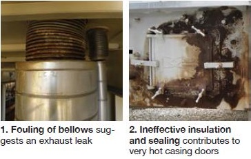 ic. Here are more of the “pearls” he shared:
- Inspect pipe hangers integral to the HRSG, the speaker noted, because attemperator steam piping and piping between modules often are omitted from the inspection program for high-energy piping (HEP).
- You can get a good “feel” for the internal condition of the insulated duct delivering turbine exhaust gas to the HRSG by listening for audible liner rattling/flapping near the round-to-square transition. Recording and analyzing the dominant frequencies can help identify the component vibrating and gauge risk. Watch for casing vibration, especially at low loads.
- When conducting a hot walkdown, take along an infrared scanner. A visual survey will find burned paint, but it does not quantify the hot spot, Wambeke cautioned. Having an IR signature will provide the temperature and enable you to track the progression of the problem. The size and shape of the IR signature, he continued, helps assess its cause—for example, missing insulation, conduction through structural members, exhaust leak, etc. Exhaust leaks typically are found at expansion joints, side doors (Fig 2), duct corners, and penetration seals.
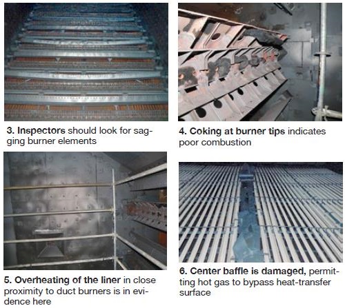
- Be sure to check the size and location of duct-burner flames, Wambeke told the group. Ideally, flames should be from 6 to 10 ft long and not visible within about 6 ft of any tubes. Flame color can tell you a lot about the combustion process, as it does for conventional boilers. Sagging of burner baffles, if found, should be addressed during next scheduled maintenance.
- Check roof seals and inspect for standing water after a rainstorm. Regarding the latter, this is a situation you want to avoid, because water will leak into any opening and contribute to progressive deterioration of expansion joints, roof seals, and doors.
- At the top of the unit, check for leaks at water-level indicators, safety valves, steam-valve packing glands, and around drum doors. Regarding the last, take no immediate corrective action without first consulting plant management and company safety personnel.
Offline inspection
An offline inspection affords the opportunity to document all findings—including the good ones. A complete condition assessment is valuable for comparison purposes during follow-on inspections. A primary goal of your effort is to identify and prioritize maintenance items—those requiring both immediate permanent repair and those having the luxury of time for corrective action. Generally, the more time available for engineering and procurement, the better and less costly the solution.
A rule of thumb is that it takes two days for an experienced engineer to inspect an F-class HRSG. Add-ons—such as tube-wall thickness measurements, borescoping, etc—extend the timeline. If plant personnel are conducting inspections, be sure to provide them checklists for the recording of key measurement and information.
Good lighting and a high-quality camera with strong flash are required for both safety and documentation. Plus, basic tools for measurement and marking are recommended.
Start your walk-around at the transition duct with a liner inspection. Look for, and correct if found, spinning washers, loose liner sheets, failed washers or studs, and exposed insulation. Verify the integrity of the expansion-joint flashing at the round-to-square transition. Check for cracking and distortion of the perforated plate and for hang-ups at guides.
Wambeke then offered what he called a “starter” list for inspecting duct burners:
- Sagging baffles or burner elements (Fig 3).
- Baffle cracks.
- Binding at wall pockets/supports.
- Condition of intermediate supports.
- Evidence of coking on burners (Fig 4).
- Overheating of the liner in close proximity to the duct burner (Fig 5).
- Fuel-nozzle cracking.
- Visual hot spots on downstream tubes.
On the speaker’s harp starter list for inspectors were the following:
- Examine tube and fin corrosion. Do you see rust flakes or fouling? What percentage of the flow path do you think is blocked? Take high-resolution close-up pictures for the record.
- Document condition of tube/header joints, if visible.
- Note condition of bulkhead, sidewall, and center (Fig 6) baffles and guesstimate the total area of gaps—if any—to determine bypass gas flow.
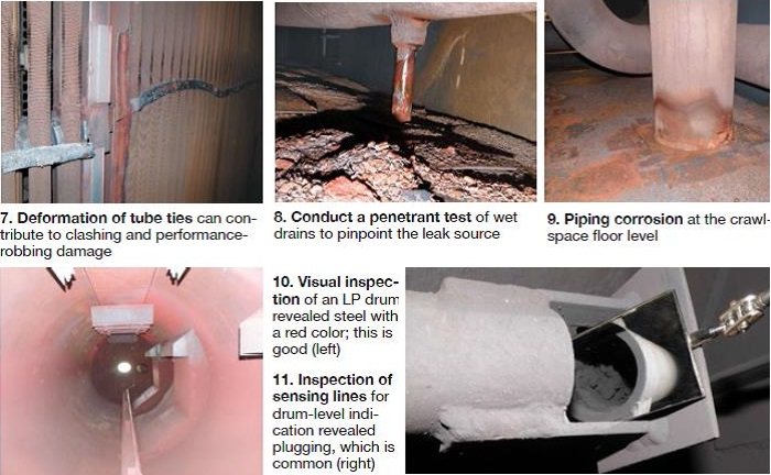
- Look for cracking and/or sagging of tube ties and any related fin damage (Fig 7).
- Make a detailed map, supported by photos, of distorted tubes in each bundle.
- Starter list for the upper and lower crawl spaces had these items:
- Characterize debris on the floor and on headers; take photos.
- Examine liner material and determine if magnetic.
- Check condition of flashing around liner penetrations.
- Look for wet spots or drips (Fig 8); examine the spray signature, if any, from leaks.
- Inspect for piping and header corrosion—especially at the liner interface (Fig 9).
In addition to inspecting for casing hotspots, standing water on the roof, and the condition of pipe hangers, all mentioned earlier, it is important to verify the condition of penetration seals. Local corrosion under the seals at the roof and floor can be problematic and often remains hidden unless the seal is removed. However, removing seals effectively demolishes them and makes replacement necessary.
Wambeke explained why you can expect to find corrosion of penetration seals:
1. Most HRSG penetration seals—typically bellows type on the hot end and fabric seals on the cold end—do not provide for drainage.
2. On stagnant lines (vents and drains), it is possible to have piping under the seal at a temperature lower than the exhaust dew point (usually 115F-120F).
3. Low-alloy steel corrodes, too. The HRSG expert cautioned about becoming overconfident with alloy piping if you have extended offline periods.
4. A systematic inspection approach was recommended. Nondestructive examination (NDE) technology can detect wall loss beneath seals without removal or demolition.
Material wastage from corrosion can be dramatic. Wambeke described a case where economizer vent piping on the roof of an 18-yr-old HRSG in a dry climate suffered a 45% loss in wall thickness and a 20% loss in diameter on adjacent hanger rods. For the first 10 years after COD the plant operated base-load; it cycled after that.
Regular steam-drum inspections are critical, Wambeke said, because they often provide the only direct access to the water-side of an HRSG. First thing to look at when you open the access door is the surface color and condition of the metal above and below the waterline (take photos). A red tint, such as that in the LP drum shown in Fig 10, is good.
Once inside, take a close look at the following:
- Mechanical condition of steam separators, and chemical-feed, blowdown, and other internal piping. If plugging issues with injection and blowdown piping are identified, tube deposits may be lurking. Plugging of level-indication sensing lines is common (Fig 11) and may be difficult to see, depending on arrangement details. Also, check the location of the sensing line with regard to downcomers. If it is too close to a downcomer, water velocity may influence measurement.
- Debris that has accumulated; note the location, type, and quantity.
- Nozzles and seams for cracking at the welds.
- IP and LP belly pans. Measure their thicknesses and trend over time; check for cracking at seams and ends.
- Verify that the door sealing surface is pristine and hinge/davit condition is good.
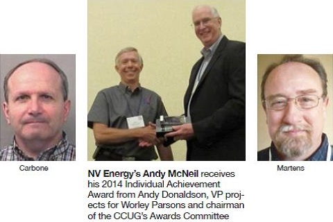
Carbone, Martens, McNeil presented CCUG’s Individual Achievement Award
Harry Carbone of Duke Energy, Ray Martens of Iberdrola Renewables, and Andy McNeil of NV Energy were recognized by the Combined Cycle Users Group with the organization’s 2014 Individual Achievement Award at its annual meeting, August 11-13, at the Westin Riverwalk in San Antonio. The award is earned by industry professionals who have demonstrated excellence throughout their careers in the design, construction, management, operation, and/or maintenance of generating facilities powered by gas turbines.
Andy Donaldson, VP projects for WorleyParsons and chairman of the CCUG’s Awards Committee, made the presentations.
Principal Engineer Harry Carbone’s contributions to the combined-cycle community began more than 40 years ago, following graduation from Purdue University with Bachelor’s and Master’s Degrees in Mechanical Engineering. In 1990, after several years at Reliance Motor, he moved to Siemens Power Corp. There Carbone led a group of engineers responsible for the design and construction of various steam- and gas-turbine projects. In 2002, he joined Duke Energy (formerly Progress Energy).
Carbone has continued to learn throughout his four decades of service to the electric-power industry. Most recently this has involved the development of skills in rotor-dynamics modeling to facilitate problem-solving. Carbone’s deep knowledge of rotating machinery has given him a lead role in many forensic evaluations of failed equipment and root-cause analyses. He understands well how the interconnected pieces of equipment function as a system and how changes to one component impact the others. Think of Carbone as an engineer’s engineer: Few in the industry have his ability to see through knotty problems and offer practical solutions.
Carbone’s technical and analytical capabilities are magnified greatly by his caring and sharing nature. He is always willing to transfer knowledge gained and lessons learned both to engineers within the Duke organization and to the industry at large through user groups and other technical meetings. His door is always open to up-and-coming engineers seeking professional advice.
Ray Martens, managing director of Klamath Cogen and Klamath Peakers, began his career in power generation in 1976 with Townsend & Bottum Constructors (since absorbed by Black & Veatch). He joined GE in 1978 as a steam-turbine field representative for both power-generation and marine applications. Martens’ involvement with combined cycles began in 1989 as the GE construction site manager for the Cardinal Cogen project at Stanford University.
After leaving GE, he worked as an independent contractor, managing steam-turbine overhauls in Puerto Rico, and spent nine years in Alaska as superintendent of Chugach Electric Assn Inc’s Beluga GT Plant. While at Beluga, Martens was active in the ABB Gas Turbine Users Group, serving on the steering committee and as chairman.
During that time, he attended his first CTOTF™ conference; several years later he was elected chair of the Siemens Roundtable. In 2001, Martens participated in his first WATUG meeting (now 501F Users Group), joining that steering committee in 2004. Currently, he is an associate chairman of the 501F Users and participated in the recent incorporation of the group.
Martens has been an aggressive, yet reasonable, challenger of OEMs during his career and has always been willing to share his experience and knowledge with other users. Evidence includes the 17 CCJ Best Practices Awards received by Klamath in the last 10 years.
Andy McNeil, NV Energy’s executive of new generation, has more than 30 years of a remarkably rich and diverse combined-cycle experience that has taken him from the Pacific Northwest, to the Southeast, to the Desert Southwest. His successes and experience range from the independent power world to the regulated utility environment.
Since joining NV Energy in 2004, McNeil has helped his company more than double its generating capacity by managing the construction and startup of the 1200-MW, 4 × 2 Chuck Lenzie Generating Station, 600 MW of quick-start peaking units, a new 500-MW combined-cycle plant at the Frank A Tracy Generating Station, and the latest addition to the company’s fleet—the 500-MW, 2 × 1 Harry Allen Generating Station.
Previously, McNeil was at Duke Energy North America for 19 years. There he was involved in various engineering, construction, and project-controls duties for such combined-cycle plants as the 557-MW Arlington Valley Plant in Arizona, the 600-MW Grays Harbor Energy Center in Washington, and the initial work for the Moapa Generating Station in Nevada, later purchased by NV Energy.
McNeil has advised other utilities and companies on a creative contracting approach to successfully build combined-cycle plants. His knowhow for developing a team, the controls that need to be in place, and the best practices to simultaneously manage the design, construction, and startup functions has resulted in his regular involvement at industry conferences, roundtables, and workshops. He also is Chairman of the Board for the Southern Nevada Chapter of the American Red Cross.
Water chemistry
The two-and-a-half hour session on water management/chemistry/corrosion control, by itself, was worth the registration fee for the meeting. Moderator Steve Royall, director of fossil and solar O&M for PG&E, and vice chair of the CCUG steering committee, had the easiest assignment: Just introduce the speakers.
There aren’t many people capable of making presentations/discussions on water treatment entertaining, but Moen, senior plant engineer, Colusa Generating Station, and Sampson, WorleyParsons’ principal technical consultant on power, water, and wastewater, certainly proved they could. The long-term colleagues were well prepared to share with users their extensive knowledge on cycle chemistry, cooling-water treatment, makeup treatment, corrosion control, clarifier problems, ZLD systems, and RO/EDI maintenance.
They came armed with more than 50 slides, virtually all crammed with valuable information for anyone in generation-plant O&M wanting to come up to speed on water. Moen and Sampson spend the better part of their professional lives on the deck plates and knew a formal presentation on all the topics they were prepared to address would have been a snoozer.
So Moderator Royall watched as they established a rapport with the attendees, identified the sources of their water pains, and plucked out slides here and there to provide guidance that offered a measure of relief in several cases.
You can benefit from the water management know-how Moen and Sampson shared with CCUG users in San Antonio by reviewing their slides, only a click away. More: Trends in powerplant chemistry, water, and wastewater, covered by Sampson at the CCUG 2013 meeting, and his slides on corrosion product transport monitoring from CCUG 2012 are valuable in-plant teaching aids.
Sampson urged that such an audit be undertaken with an open mind and a willingness to make changes where necessary. A 2014 Best Practices Award recognized the efforts of PG&E’s Colusa and Gateway Generating Stations in this regard. It provides a first-hand look at the extent of the assessment process and positive actions taken to assure that the plants are capable of maintaining availability and reliability at the highest levels possible.
In dollars-and-sense terms, a benefit of a cycle-chemistry evaluation and overhaul program is it almost always reduces life-cycle O&M costs. Said Sampson: It’s certainly less expensive than a forced outage. Some illustrations offered:
- Bad cooling-tower chemistry is conducive to poor heat transfer and/or failed condenser tubes.
- Bad chemistry in an air-cooled condenser, depending on design, can mean air leaks and significant transport of iron into the steam cycle.
- Poor HRSG chemistry reduces heat transfer and causes tube failures.
- Poor chemistry in the closed cooling-water system is a precursor of bearing failures.
As for the “right time” to do an audit, Sampson said “now,” pointing to the increase in water-use restrictions and higher prices, plus the bans in many areas on plant liquid discharges—all of which have added to the already significant burdens on owner/operators. To prepare for a third-party review, the consultant suggested plant personnel review their best practices for such things as the following:
- Water-use survey and ongoing monitoring.
- Demand reduction. Examples include reducing boiler blowdown, increasing cycles of concentration, etc.
- Onsite treatment of drains for reuse.
- Treatment and use of municipal and industrial wastewaters for plant makeup.
- Alternative uses for plant wastewater streams.
- Sampling and pretreatment of ground and surface waters.
Cooling water. Top plant efficiency depends a great deal on the performance of the heat rejection system. Moen spent quality time reviewing the key performance indicators (KPIs) for cooling towers—including approach to wet bulb; difference between the actual cold-water temperature and the design value; tower capability, actual performance versus design; chemistry limits and control capability, etc.
The speaker suggested attendees use the Cooling Tower Institute “Blue Book” software product for calculating performance parameters, such as the Merkel equation. CTI’s ToolKit represents industry consensus for cooling-tower design and performance evaluations, he said. The cooling-tower performance section of the Moen/Sampson presentation is robust and valuable for plant use.
Moen said that any plant waste stream with a lower TDS value than the cooling-tower water should be returned to the tower, which makes it something like a waste sump. If you do this, be sure your tower is equipped with state-of-the-art controls because water quality is variable.
Open discussion. Here are a few takeaways from the robust exchange between the speakers and attendees before the coffee break:
- Regarding wet chemistry, Sampson said the only value of it in an operating plant today is to confirm the accuracy of online analyzers. Best practice: Run demin water through all analyzers when the plant is shut down.
- Proper staffing and training is important, Sampson stressed. Employees have to care about chemistry, he said, and to know why they are taking measurements. It’s important for the staff to know the instrumentation and processes are accurate and reliable.
- The Chemistry Performance Index was introduced as a valuable tool for keeping plant chemistry within specifications. CPI data should be analyzed weekly, Sampson said, and daily figures should be compared to that baseline. If the daily and weekly numbers deviate by more than 10%, the equivalent of a root-cause analysis (RCA) should be implemented to determine why.
- One user mentioned a sudden drop in feedwater pH at his plant and wanted to know the likely cause. Sampson said a glycol leak into the steam cycle would do what he described. He recalled an incident where one gallon of glycol leaked into a drum and dropped the pH from 9.5 to 4.5. It took days to figure out what had happened.
- Once you get glycol into a steam system, the water consultant continued, it’s almost impossible to get it out. Glycol breaks down into a weak mineral acid in the drum and can drop pH to 4.5 or below. The only practical way to correct the problem is to drain the boiler and refill it.
- The impact of seasonality on clarifier treatment was another discussion topic. It was said that different coagulants and polymers might be required at different times of the year. Regarding uses for sludge, a suggestion was to use it for capping a landfill or as a fertilizer or fill in farming.
ZLD. Following the coffee break, session focus shifted to zero liquid discharge. ZLD was a hot discussion topic given its interest by regulatory agencies. If you are unfamiliar with it, picture a system that allows water to leave the site only as a gas (steam or water vapor); dissolved solids are concentrated until only solid waste remains. The 25 slides on ZLD in the presentation (scan QR 1) are an excellent primer on the subject.
Sampson strongly recommended that ZLD be considered only as a last resort. Discharge to others, if possible, he said. According to his calculations, a basic 500-gpm ZLD system will cost about $50 million (net present value) over 20 years.
Both Sampson and Moen have deep experience with ZLD, and the scars to prove it. They reviewed some of the pitfalls to avoid in the design and operation of these systems, including the following:
- ZLD system performance degrades over time and this should be factored into the design. Two 60% modules were suggested, and that assumes confidence in the plant water balance.
- ZLD systems must operate with constant chemistry and flow, unlike wastewater treatment systems which are designed to receive different plant streams with variable flow and chemistry with the goal of providing an acceptable ZLD systems do not turn up or down, or on or off, well. They cannot tolerate deviations from design chemistry and must be monitored continuously.
- It would be a mistake to assume a ZLD system can be operated by the same number of personnel as a conventional water treatment plant. Here’s the staffing Sampson and Moen recommended for a simple ZLD system: A minimum of seven to nine experienced people— including a manager (plant chemist or ZLD O&M manager), a dedicated ZLD operator 24/7, and half time for a mechanic and I&C technician. Complex ZLD designs require 12 to 14 extra people—including a manager, two operators 24/7, and a full-time mechanic and I&C tech.
BOP
There were plenty of shared experiences beyond steam systems at the CCUG meeting, with dozens of combined-cycle plant managers and staff tackling a wide range of issues—including those associated with control systems, advanced monitoring and diagnostics (M&D), transformers, and NERC compliance. A summary follows.
Paul Griffin, VP, Doble Engineering Co, provided a veritable blueprint for conducting an asset health review of transformers—one aimed at discovering problems early, determining criticality and priorities, identifying patterns among transformers, informing your sparing philosophy, and minimizing risks to reliability and of catastrophic failures.
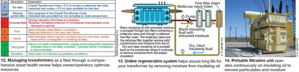
Objective of the review is to assign each transformer an overall rating (scale of 1 to 5) and a condition code (green, orange, red, or blue), Fig 12. Like so much combined-cycle equipment, this is more important for units undergoing a high degree of cycling, or loading and unloading of the transformer.
To do this properly, a great deal of information is required, essentially as much as is known about the transformer as possible, comprising external inspection (including thermal imaging), laboratory testing, electrical testing, design review, historical operating data, fleet historical data, vendor advisories, online and offline tests, conference papers, trouble and failure reports (faults and short circuits), and input from O&M personnel.
The overall rating is a composite of sub-codes for results from routine or specialty tests. These include mechanical tests, electrical tests, insulation ageing, dissolved gas analysis, partial discharge tests, and oil-condition codes determined from corrosive sulfur- and metals-in-oil tests.
Axel Wegner, technical manager, C C Jensen Inc, showed the group how to maximize transformer insulation life by proactively and continuously maintaining low levels of oxygen and moisture in the transformer oil with a recirculating cleaning treatment system. Instead of running to failure or regenerating transformer oil during planned outages, Wegner recommends regenerating online (Figs 13, 14). Depending on the initial contaminant levels, the system might run for several hours or for three to four months to achieve a “bone-dry” condition. Wegner backed up his recommendation with numerous graphs showing how different levels of contaminants lead to different deterioration rates.
 Jason Makansi, president, Pearl Street Inc, addressed challenges with modern control systems, which he listed as obsolescence; integration, convergence, and embedding M&D, predictive, and simulation capabilities; the human-digital interface; and remote versus onsite locations for M&D and control.
One of the big immediate issues, he said, is “Combined-cycle plants installed during the big wave from 1997 to 2004 are maturing, but the digital components don’t last nearly as long as the physical plant.” Several options are available for upgrading plant control systems, which don’t necessarily have to involve a traditional automation platform.
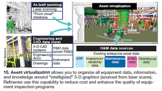
In an attempt to show what the future might look like, Makansi focused on 3-D visualization technology. Converting laser-scan photography of actual equipment into intelligent graphics allows you to organize all the relevant data, information, and knowledge around the as-built environment. INOVx Corp, Irvine, Calif, specializes in this software and capability and is transferring its experience and applications from the petrochemical industry to the power industry. Refineries, in particular, are finding significant value from “asset virtualization” (Fig 15) for reducing costs and enhancing the quality of equipment inspection programs.
Makansi encouraged the audience to imagine life at the plant where all information is available on a handheld device, from a Google glass type of device, or an “info visor screen.” He went on: “Think about how your car is connected remotely to data and your engine is run and diagnosed with digital technology, how people today are glued to their phone or i-pad screens, and how smart technology is coming to your home.”
He argued that, similarly, control systems will become more of a “digital space.” Makansi’s recommendation: Every facility, whether being planned, designed, or already operating, needs a design specification, a lifecycle blueprint, that holistically accommodates this digital space and looks at all of the functions, controls, M&D, cybersecurity, and digital pieces and parts, from a common vantage point.
Mike Gabriel, director of critical infrastructure compliance, EthosEnergy Group, a joint venture of Wood Group and TurboCare, offered a plant perspective on NERC (North American Electric Reliability Corp), FERC’s “cop on the beat” for electric system reliability. Here are a few of the salient points made by the speaker, in the opinion of the editors:
- NERC’s Reliability Assurance Initiative (RAI) is voluntary, but if you don’t participate, you open your facility up to more frequent audits and audits of greater scope.
- Time is of the essence. RAI is part of NERC’s Critical Infrastructure Protection (CIP) v.5, scheduled to be in force April 2015.
- Under CIP v.5, all plants are “critical” but there are low, medium, and high designations. Under CIP v.3, only 15% of registered plants were deemed critical. One of Gabriel’s slides will help you determine if your plant is destined to be classified low, medium, or high.
- Training your people is a critical part of the process.
- Protection systems include protective relays which respond to electrical load quantities, communication systems for correct operation of protective functions, voltage and current sensing devices providing inputs to protective relays, station DC supply associated with protective functions, and control circuitry associated with protective functions.
- Protective system equipment must be identified along with the compliance protocol governing it.
The presentation included several slides detailing the maintenance activities and intervals recommended for protection system components and subsystems. More standards are coming for verification of excitation and load control models, operations personnel training, disturbance monitoring, and generator relay load-ability. The lessons learned from the PG&E Metcalf substation attack in April 2013, also detailed, are sobering, and provide a potential glimpse into mitigation efforts which are required after a serious incident. This and the other presentations are available on the CCUG website at www.ccusers.org. CCJ
