Managing a powerplant for top performance can be a thankless task. You always seem to be at odds with those controlling the purse strings who don’t fully understand how generating assets work. So you write a business case to illustrate that a better balance sheet would be possible were a given upgrade funded.
Sometimes difficult to get attention the first time you float an idea up the “chain of command.” Important not to lose heart. Resubmit your idea with each year’s budget until it gains traction. There’s a better-than-even chance it will be implemented if the positive supporting assumptions used in your analysis have not changed and/or the plant is not sold during the gestation period.
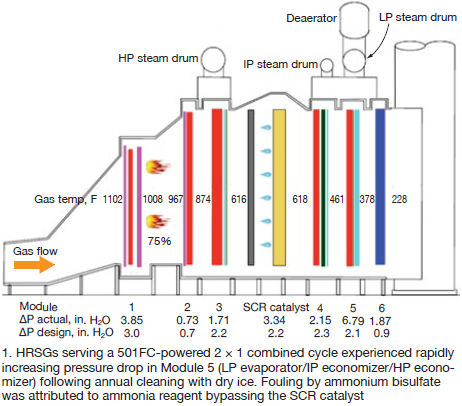
Case in point is a 2 × 1 combined cycle powered by W501FC+ gas turbines that had experienced a high exhaust-gas pressure drop through its HRSG’s fifth modules since plant startup in 2000 (Fig 1). The fifth module includes the LP evaporator, IP economizer, and HP economizer sections. There was one change in ownership over the years.
Each of the HRSGs is equipped with an oxidation catalyst and SCR to keep CO and NOx emissions within permit limits. The gas-only plant’s continuous full-load rating is 480 MW with duct firing at a maximum ambient temperature of 120F and 15% relative humidity.
Majority of the fouling in Module 5 was occurring in the LP evaporator section, the tubes contacted first by exhaust gas flowing through the module. Cause of the high pressure drop was ammonium bisulfate (ABS) deposition in the tube bundle, caused by high local ammonia concentrations that pass through the SCR in those areas (slip). Ammonia, as a 28% aqueous solution, is injected at a rate of 150 lb/hr at plant design operating conditions.
The HRSGs were cleaned annually by dry-ice blasting, but the pressure drop quickly increased after cleaning, from 2.1 in. H2O (clean condition) to 6.8 in., or more. Fig 1 gives typical data taken from the plant DCS when Module 5 was experiencing high gas-side pressure drop attributed to fouling.
Incentives for mitigating ABS deposition include the following:
-
- Extend the interval between tube cleanings, reducing cost.
- Reduce gas-turbine backpressure, thereby increasing output and revenue. The nominal 5 in. H2O increase in pressure drop through Module 5 was costing this plant, in round numbers, between about 1 and 1.5 MW in output.
Concord Environmental was contracted by the plant owner to tune the ammonia injection grid (AIG) with the expectation that improving ammonia distribution across the SCR would eliminate the fouling problem. Bill Gretta, PE, senior VP/engineering director, would lead the company’s effort.
However, AIG tuning alone failed to improve the ammonia distribution. Physical changes in the HRSG were necessary to reduce ABS fouling downstream of the SCR.
Concord Environmental developed a computational fluid dynamics (CFD) simulation of the entire HRSG to determine the cause of the poor ammonia distribution. Gretta said the company also was tasked to develop and implement the necessary design changes once the root cause of the fouling was determined.
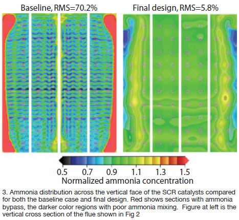
CFD identifies problems. Without delving into the complexities of the full-system CFD model, suffice it to say that detailed contour plots of exhaust-gas temperature, pressure, velocity, and ammonia distribution were developed throughout the entire HRSG—including the AIG grid. The model found that although the velocity distribution was quite uniform at both the CO and SCR catalyst inlets, the ammonia distribution was very poor at over 70% RMS—well beyond the goal of 10% RMS—at the inlet to the SCR catalyst.
The bottom of the CO catalyst support structure was of a design that allowed large areas of recirculation. Ammonia quickly collected there and along the sides of the HRSG where the casing expands and additional areas of recirculation existed. These two regions cause the ammonia to be “pulled” in and stay concentrated near the bottom and vertical walls before being propagated downstream into the SCR catalyst. Such problems typically are caused by too few injection holes in the AIG and the lack of mixing of the ammonia and the flue gas (Fig 2).
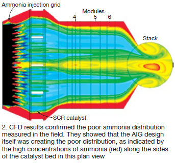
Concord Environmental’s CFD modeling confirmed that ammonia was concentrating heavily along the side walls as well as in the top and bottom corners of the catalyst bed. However, the CFD model revealed that the AIG design itself was creating the poor distribution with high concentrations along the sides of the catalyst. The AIG supplied with the HRSG was located 4 ft downstream of CO catalyst, in a section of the HRSG casing expanding towards the SCR catalyst.
The solution was to move the new AIG 3 ft upstream so the revised AIG centerline was 1 ft downstream of the CO catalyst (the gray module immediately upstream of the AIG in Fig 1) in a uniformly spaced arrangement. CFD modeling also showed that adding mixing baffles to the upstream side of the newly located AIG greatly improved local mixing. The lance penetrations through the HRSG casing remain unchanged thus causing a jog in the AIG lances in the upstream direction. This eliminated the need to modify any external piping.
Mixing of ammonia downstream of an AIG is highly dependent on the local turbulence level in the gas; thus the holes in the new grid are spaced over its entire 33-ft length. Plus, all holes point directly downstream, unlike those in the original design. The turbulence level downstream of the fine-pitch CO catalyst is very low; the new baffles greatly improve ammonia mixing.
In addition, there was a large wall at the base of the CO catalyst bed which created a large recirculation zone along the floor. The CFD model was used to design plates that were added around the perimeter of the CO catalyst to direct exhaust flow directly into the AIG and avoid sneakage along the sides, top, and bottom into those recirculation zones.
With the addition of AIG mixing baffles and CO catalyst ducting baffles, gas flow from the CO catalyst now flows uniformly into the AIG injection area. When compared to the baseline AIG pressure drop, the new design added only 0.2 in. H2O. More importantly, the final CFD design reduced the ammonia velocity distribution to 5.8% RMS, well below the design goal of no more than 10% RMS (Fig 3).
Accelerated construction. Concord Environmental was awarded the design, supply, and installation contract for removing the old AIG and installing the upgrades after the CFD modeling report was completed and the results presented to the plant owner in early October 2017. However, the owner had earlier scheduled a plant outage for Nov 1-14, 2017, so there was less than a month available to design and fabricate the new AIG and baffles, select, and mobilize the contractor at the job site, and complete installation.
Concord selected a non-union contractor based on its experience and ability to meet the project’s compressed schedule. The new AIG tubes and baffles were quickly fabricated by one of company’s preferred fabrication shops, arriving onsite October 30.
By that time, the contractor had mobilized onsite and had completed the demolition and removal of the old AIG. Construction crews worked two 12-hr shifts to complete the AIG upgrades for both HRSGs on schedule. Installation of the new AIG and baffles was completed November 13, one day ahead of schedule.
Operating data after startup. After the outage was completed, initial startup data showed significant reduction in ammonia flow, which translates into reduced localized ammonia concentrations (table).
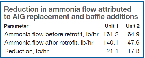
Ammonia usage has decreased by 15% to 25% depending on load, and pressure drop in Module 5 has held steady for the past six months based on station instrument readings. The result has been a reduction in plant operating cost through the reduction of ammonia usage, avoiding the operating efficiency loss experienced with ABS fouling of Module 5, and will greatly reduce the future cost to clean the ABS from Module 5 tubes.