

Continuous blowdown realignment saves water, chemicals
CI Power Cogeneration Plant
Owned by California State University Channel Islands
Operated by NAES Corp
30 MW, gas-fired, 1 × 1 combined-cycle cogeneration plant located in Camarillo, Calif
Plant manager: Jeffery Smith
Challenge. The Channel Islands Power Cogeneration Facility, a 30-MW combined cycle equipped with a single LM2500, a Vogt Power International HRSG, and a Shin Nippon Machinery Co steam turbine/generator, operated for 30 years under a baseload power purchase agreement with the local utility. In April 2018, it began operating under a dispatch-style PPA.
The change in operating profile required keeping the HP and IP drums warm to meet startup times specified in the new PPA. Heat is provided by a sparging system which injects steam at the bottom of the steam-drum risers, thereby developing a natural-circulation pattern to sustain chemical mixing. The use of sparging steam increases drum water levels over time. Operators managed drum levels by venting steam from the tops of the drums and by opening the bottom drains when necessary.
The process of adding and draining water dilutes the boiler chemicals necessary to protect drum internals. Continuous injection was required to maintain chemistry levels within the baseload target ranges.
Solution. Plant personnel began looking for ways to recapture the water from the blowdown/venting process. In reviewing the system configuration, investigation of the continuous blowdown system (CBS) showed that during baseload operation it was designed to recover some steam. After further discussion, this question arose: Could water be directed to the deaerator (DA) rather than just the steam?
During the baseload operating period, continuous blowdown valves rarely were used; most sat idle. Most years they only were operated during annual valve maintenance. The blowdown control valves and associated manual valves were checked to verify full working capability. After a little maintenance, the system was cleared for use.
Starting with the IP drum, the system was tested to prove the concept of pushing the water from that drum to the DA. It took a couple of tries to get it to work because IP drum pressure was not high enough to overcome the water-column head pressure and DA steam pressure. After a couple of adjustments (closing the drum vent and boosting sparging-steam pressure), water could be moved into the DA via the steam path.
The chemical supplier was contacted to discuss the possibility of shifting control ranges for phosphate, pH, and O-alkalinity under the new operating profile. Plant personnel were told they could reduce the phosphate range from 10-20 ppm to 1-2 ppm. pH also would adjust slightly.
During warm standby, the chemistry levels were low enough to assume that there would be little to no chemical deposition in the feedwater system. Values were in the ppb range because of their dilution in the feedwater system. This would allow the minute amount of chemicals in the steam drums to flow through the DA to the standby boiler feedwater pumps (BFP) and finally into the standby boilers.
During the first few days of September, the standby BFP discharge conductivity was monitored; no change was noted. The chemistry levels in the drums of the standby boilers remained steady. The amount of chemicals transported out of the HP and IP drums did not significantly affect standby-boiler drum chemistry over the short term.
The chemical supplier also recommended that the plant monitor iron levels in the HP and IP drums. Silica typically was monitored to protect steam-turbine blades. Chemistry protocols were adjusted to check for iron when in warm standby and for silica when operating. Three months of iron sampling gave no indication of issues with the warm-standby chemistry protocol. Iron levels in the HP and IP drums are consistent with historical iron levels throughout the condensate and feedwater systems.
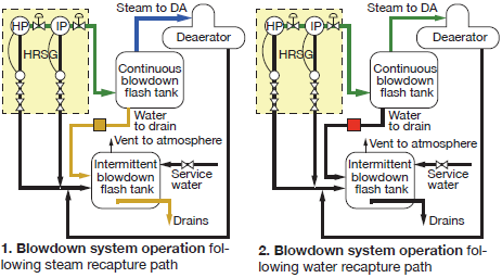
Fig 1 shows how the CBS works during baseload operation. Hot water moves from the HP drum to the IP drum to the flash tank (green circuit). Here the thermal drain trap holds the hot water, allowing it to steam off. Steam is routed to the deaerator (blue); water is released to drain (yellow) when the thermal drain trap cycles. In this operating profile, the control valves on the steam drums were programmed to operate based on conductivity levels in the drums.
Fig 2 illustrates the alternative operating condition for the CBS. The thermal drain trap (red) is isolated from the drain line. Hot water moves from the HP drum to the IP drum to the flash tank to the deaerator (green). For this operating profile the control valves were reprogrammed to operate based on drum level. No water or chemicals are routed to the drain.
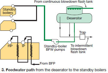
Fig 3 shows the water path from the DA to the standby BFW pumps to the standby boilers (green). A detailed review of the water flow path shows that there are no system components—such as attemperators—that could be impacted by the introduction of low levels of phosphates.
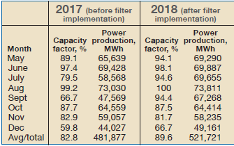 Both May and September were zero-dispatch months. During May the plant was maintained in warm standby utilizing venting and blowdown operating profile described in Fig 1; September used the repurposed CBS described in Fig 2.
Results. The table at right compares operating parameters and chemical consumption for warm standby operation using the venting/blowdown scheme (May) and the repurposed CBS (September).
Project participants:
Raul Perez, Dale Helin, Ben Barraza, Pete Corral, operators
Steve Hughes, I&E Tech
Michael Mackey, Nalco
