

By David Addison, Thermal Chemistry Ltd, and Steven C Stultz, Consulting Editor
The Australasian HRSG Users Group annual meeting (AHUG2016), held November 15-17 in Sydney, Australia, covered a full range of topics—including extended inspection intervals, performance improvement, plant-specific updates, cycle chemistry, and advanced materials.
Each annual conference, combined with its associated workshops, seems to develop an over-riding theme—one that threads its way through the presentations and on-floor discussions. For AHUG2016, the recurrent theme was risk-based inspections (RBI), as it was at the ACC Users Group meeting in Dallas last fall.
By better managing the inspection process, so the discussions went, owner/operators can perhaps extend outage schedules without harm to key equipment, reduce downtime, and increase revenues. But such an effort requires both precision and management.
Gatherings like AHUG2016 help generate and maintain these strategies by discussing specific ideas, methods, experiences, and questions. Similar user meetings are held in Europe, Russia, and Canada—and ideas are shared.
Extended inspection intervals demand risk-based approach
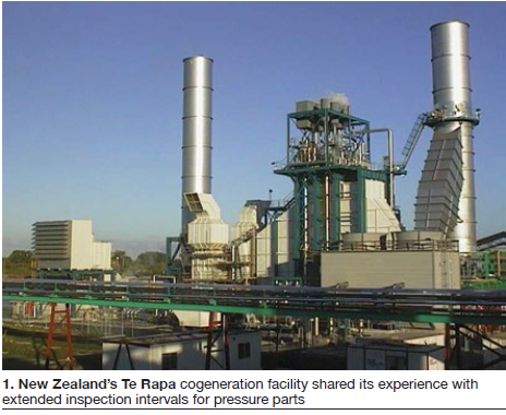
Mark Utley, Contact Energy (CE), New Zealand, and a member of the AHUG steering committee, led off Day One with a detailed look at risk-based inspection methods at three plants: Taranaki Combined Cycle, Te Rapa Cogeneration (Fig 1) and Otahuhu Combined Cycle B.
In New Zealand, boiler and pressure-vessel regulations are governed by the Health and Safety at Work Regulations, most recently updated Feb 15, 2016. A pressure equipment inspection program is based on the recommended in-service inspection intervals prescribed by Australian/New Zealand Standard 3788, “Pressure equipment—In-service inspection.”
These intervals can be extended through an approved quality management system that meets the requirements of both AS/NZS 3788 and Appendix F of the “Approved Code of Practice for Pressure Equipment,” published by the New Zealand Occupational Safety and Health Service (Dept of Labour). The base inspection period (starting point) is one year. Extending this can save both time and money.
The covered pressure equipment inspection programs are divided into three parts:
- Boilers and pressure vessels.
- Piping.
- Protection systems—such as safety valves.
A piping example: Risk-related features can include high-energy-piping (HEP) weld condition, flow accelerated corrosion (FAC), corrosion under insulation, and system chemistry.
To develop the RBI approach, personnel must identify all relevant features of the system, then collect and record clear and comprehensive baseline data. And sometimes, stated Utley, “when you start the inspection you begin to find completely unexpected problems—such as inaccurate construction data.”
He then offered some sample priorities based on perceived risk:
- Areas of highest stress.
- Piping at the HRSG end (more stressed than at the steam turbine end).
- Terminal point and dissimilar metal welds.
- Areas not previously recorded.
- Undocumented welds.
- Areas of non-ideal geometries.
- Pipe-to-elbow welds.
- Areas repaired.
- During fabrication.
- During operation.
- Other concerns.
- All weld types.
- Chemistry regime (versus original design assumptions).
Throughout the RBI process, focus on these fundamental questions, the speaker said:
- 1. Do we understand what can go wrong?
- 2. Do we know what systems we have to prevent this from happening?
- 3. Do we have information to assure us that our systems are working effectively?
Turning to the three subject plants, Stage One risk-based assessments considered the following:
- Materials of construction.
-
- Any materials not well-known to contractors (P91, heavy-wall stainless steel, etc).
-
- QA during construction.
-
- Materials and consumables control, weld fit-up inspection, completeness of records, contractor reputation.
-
- NDT methods used.
-
- Ability to detect defects—RT (radiographic testing) on heavy-wall components, etc.
-
The conclusion: Baseline inspection was needed in the high-energy Grade 91, 22, 11, and HT (heat-treated) stainless piping systems at two of the three plants.
Stage Two assessments focused on pressure equipment, and evaluated the following:
- Mechanical features that can develop into defects over time, and/or
- Process mechanisms that can change the pressure equipment condition and threaten its integrity.
This led to several subsets of inspection criteria for the same two sites. Precise details were given.
Next, an overall inspection and test plan (OITP) for a nominal 10-year period for pressure equipment (including boiler and piping) was developed, to be reviewed at least annually. The OITP must be all-inclusive and documented, with a clear audit trail. Application is then made to the New Zealand regulators.
For these three plants, regulatory reviews resulted thusly:
- Te Rapa. Moved from one-year to three-year internal inspection interval to match major outages.
- Taranaki. Currently moving toward a three-year interval.
- Otahuhu B. Shut down.
Ongoing compliance conditions also include:
- ISO 9000 quality management system continuance.
- Annual audit by recognized inspection body.
- Extension applies only to pressure equipment scheduled in OITP.
- Any changes to equipment or process must be reported and reviewed.
To adjust to the new schedules, Contact Energy cycle-chemistry improvements are now taking place related to layup and storage procedures, improved instrumentation levels and equipment, and full compliance with IAPWS-recommended online chemistry monitoring of feedwater, evaporator, and steam circuits.
During questions and comments (some focused on local regulatory bodies and responsibilities), Utley offered a sharp and direct summary: “The owner/operator is ultimately responsible,” he affirmed. “If you need to push plants harder, then an RBI process can give you confidence that you have the right information to do so.”
Dry-ice tube cleaning
Joel Williams, Precision Iceblast Corp, provided a specific strategy for increasing efficiency and output, and decreasing costs: HRSG tube cleaning with dry-ice blasting. He first compared dry-ice particles with the more traditional use of abrasive media, which can damage the metal substrate. Dry-ice particles do not.
Carbon dioxide (CO2) is now used effectively on the four primary types of buildup on HRSG tubes: ammonia salts, sulfate deposits, iron oxide deposits (corrosion), and insulation materials (Fig 2).
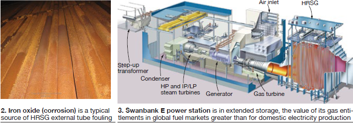
If such fouling is not removed, consequences often include increased gas-turbine (GT) backpressure, reduced thermal efficiency, and particulate emissions during startup.
Examples were reviewed, including common methods of determining when to clean:
- Visual inspection.
- Backpressure readings.
- Stack temperatures.
Revenue and cost impacts were listed and discussed.
Williams then put on his sales hat. Precision Iceblast, he said, also offers deep-cleaning equipment specifically designed for HRSGs. Bundles with up to 24 rows of tubes, he reported, have been cleaned effectively and without tube damage.
Specific questions clarified CO2 shelf life, remote site applications, and crew safety.
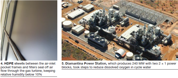
Swanbank long-term storage
Stanwell’s 375-MW Swanbank E Power Station in Queensland (Fig 3) was removed from service in December 2014, primarily to benefit from the increasing world-market value of its gas entitlements. The unit’s return to service (originally 2017) has now been extended to 2018, increasing various long-term storage requirements and risks.
Stanwell Corp’s John Blake, a member of the AHUG steering committee, explained how the site continues to implement and expand comprehensive cold-storage and preservation techniques for all systems. This was consistent with his 2015 presentation that explained how the small caretaker team does not simply set and forget. They remain alert and look for improvements.
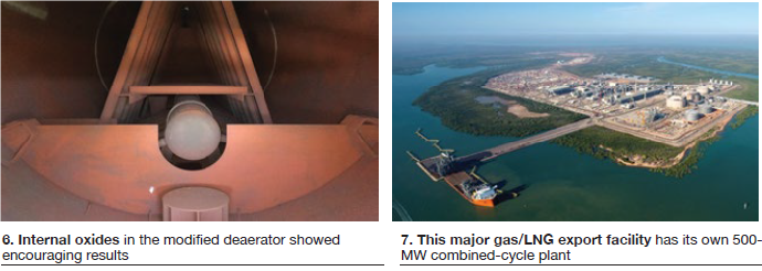
Some of the 13 dehumidifiers have experienced component failures, so crossover ducts are now installed for both redundancy and to maintain air turnover during repairs. Also, initial attempts to make an air-inlet duct balloon seal completely were not successful. HDPE sheets offered improved seals. Specifically, 600 1.5-mm sheets were installed between the pocket frames and filters, holding relative humidity (RH) below 10% back to the GT exhaust (Fig 4).
The presentation and discussion generated many questions and comments on a range of topics, including these:
- Rainwater ingress through external casing (and corrosion under insulation).
- Roof leakage.
- Separation and measurement of the dehumidified-air (DHA) circuits.
- A growing interest (globally) in film-forming amines in place of DHA.
- GT bearing protection.
- Generators, breakers, and related equipment concerns.
Blake’s summary statement fit the venue: “Long-term storage has a number of unknowns. It is good to come to these user group meetings to share our experiences and learn from others.”
Penetration and casing seals
Because there are multiple expansion-joint locations in combined-cycle plants, there are also common problems, increasingly aggravated by two-shift and cycling operation. HRSG penetration- and casing-seal degradation was the next topic, offered by Dekomte’s Jon Tarrant.
Topics included locations, applications, and OEM designs. Then came the identification of typical failures, followed by repairs, replacements, and retrofits. Example: For steam-line side-wall metal-bellows penetrations, Tarrant suggested, “Fabric retrofits offer advantages of lower cost, quick installation, and no requirements for NDT or heat treatment.”
For OEM axial metallic bellows, which allow only minimal lateral movement, distortions and corrosion are common. Replacement costs are also high, so fabric retrofits can become a viable option. Retrofit details (bolsters, fabric, clamp bands) were presented.
Fabric retrofits are also suitable for packed-gland labyrinth seals, an upgrade to counter high maintenance, gas leakage, and typical water ingress. Design specifics were reviewed.
HRSG insulation topics included typical formats and maintenance procedures, and an update on pumpable insulation. Typically, work on liner plates (and insulation) requires unit shutdown. One option is pumpable insulation, injected from the outside of the HRSG (after ensuring liner plates are properly in place). Such material is a mix of short fibers dispersed in high-temperature binders which, upon drying, produces a strong insulation structure with low thermal conductivity (with good adhesion, high melting point, and low shrinkage).
The unit remains online while the product is pumped into place. Pumpable mastic is available in both regular and bio-soluble forms.
An interesting caution followed during discussions, supporting close inspection and possible component replacement. If bellows have failed near HRSG drains, the area could be an unsafe work environment with hot gas leakage. Hot gases can also damage electrical equipment.
Steam and water sampling
Following some open-floor discussions, John Powalisz, Sentry Equipment Corp, covered current steam and water sampling issues related to cycling operation, reduced plant staffing, and corrosion products (metals) transport leading to erosion and corrosion.
Sampling issues specific to combined cycle plants, he explained, are:
- Flow is too high during startups.
-
- High temperature impact on equipment.
- Inconsistent data (pH, for example).
- Sample flow interruption by thermal valve trips.
-
- Flow is too low during low load, startups, or with plugging.
-
- Erroneous data, no flow to analyzers.
- Air ingress causing false numbers (carbon content).
-
The goal is to control the important parameters of velocity, pressure, and temperature for both online instrumentation and grab samples. Automated sampling racks, for example, should offer temperature control monitoring, pressure-reducing-valve (PRV) control, and the ability to set flow rates.
One interesting bottom line: “People are scarce; pressure and load changes are frequent,” said Powalisz. Limited staff is available to operate the sample panel during transients. Therefore, it is good to automate (and/or outsource) as many functions as possible.
Iron-transport sampling continues as a significant issue. During comments and discussions, it was noted that iron transport indicates suboptimal cycle chemistry control and should be controlled at the source in the first instance through the correct application of cycle-chemistry guidelines—such as the IAPWS technical guidance documents (TGDs). More on these guidelines below.
Trying to address iron-transport issues at the sampling rack does not address their root cause, it was stated, and the risk of major component failures caused by FAC will still remain. An optimized cycle-chemistry program for the feedwater and evaporators of a CCGT plant will result in very low total-iron transport rates and very low total-iron levels in the sample lines.
Oxygen control
David Williams, APA Group, followed with a user case history on oxygen control for new HRSGs, describing the company’s 240-MW Diamantina Power Station in Queensland (Fig 5), which opened at the end of 2014 with two power blocks.
After commissioning, cycle chemistry was within acceptable limits and controllable, except for feedwater dissolved oxygen (3 ppb versus the specified 5 to 20 ppb). Cycle chemistry control was achieved through condensate and feedwater dosing and blowdown. Unit chemistry was designed to operate as an AVT(O) system. (Proper oxygen in the feedwater economizers is critical to allow formation of protective layers, minimizing FAC.) After 12 months of operation, a 3-mm wall-thickness loss had occurred in the HP and LP economizers. Focused and comprehensive investigations began.
A critical discovery: The deaerator venting arrangement had not been installed as recommended by the manufacturer. Modifications were made first to one power block, and dissolved oxygen control in that block was possible (Fig 6).
Investigation after 12 months showed no evidence of FAC. Iron-transport studies showed a decrease in total iron levels (soluble and particulate), and magnetite levels through the condensate system were noticeably reduced. Inspection timing was then extended based on a risk-based approach.
Applying chemistry to RBI
One of the largest industrial projects in the world is a major gas/LNG export facility that includes a large combined-cycle plant (Fig 7). Petrofac’s Hayden Henderson, a member of the AHUG steering committee, described this 500-MW power complex, part of the Ichthys LNG project at Bladin Point, Darwin (Northern Territory) led by Japan’s INPEX Corp.
The complex features five GE Frame 6 machines with HRSGs, and three 100-MW steam turbines fed by a common steam header that connects to three isopentane utility boilers. Overall plant design features N+1 redundancy so that turbine trips do not affect LNG production. The plant supplies power only to the LNG complex and is not grid-connected.
The task discussed at AHUG2016: A collaborative effort to design a risk-based inspection program for all pressure vessels, piping, and utilities within the boundaries of the combined-cycle plant, and to extend inspection intervals from 12 to 36 months.
The goal:
- Highlight all relevant degradation-mechanism likelihoods and consequences in all piping and pressure equipment, and
- Create inspection plans, drawings, and written schemes of examination for all piping and pressure equipment.
Regulations would allow the extension if the proper RBI program were used, the boiler had adequate water-treatment facilities, and the equipment had a demonstrated history of reliability.
Henderson’s RBI presentation focused on station chemistry to define the inspection plan.
At project launch, data were limited, power demand and operating modes were not known, cycle-chemistry guidelines (from the EPC contractor) were not adequate, and co-owner (UK-based Petrofac Corp and INPEX) methodologies focused on oil and gas facilities, not combined cycles.
Chemistry guidelines were critical. IAPWS and EPRI guidelines were reviewed leading to fixed integrity operating windows (IOWs) for both feedwater and boiler chemistry. All decisions were made through workshops in a controlled collaborative process, targeting international best-practice cycle chemistry. NDT inspection would be completed at least twice within the first 36 months.
The IOWs are now being developed into a cycle-chemistry guidance document. Provided the IOWs are met, the inspection plan is executed, and no defects are found, the boiler internal inspection frequencies can be extended to match hot-gas-path (HGP) inspections.
During discussions, AHUG Chairman Barry Dooley of Structural Integrity Associates Inc, offered an interesting Rule of Thumb: “In these types of plants, corrosion is either on or off; it’s off if you get the chemistry right.”
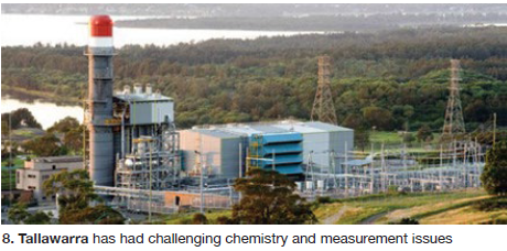
Cycle chemistry at Tallawarra Power
Ivan Currie, Energy Australia, then presented cycle-chemistry activities at the 435-MW Tallawarra Power Station (Fig 8) where he labeled the pursuits “a kaleidoscope.” The facility was commissioned in 2009 for baseload operation, but is now transitioning to flexible operation. The plant operates with an oxidizing feedwater chemistry and trisodium phosphate in the evaporators. It is saltwater-cooled.
Unstable chemistry (especially evaporators) was making proper dosing difficult, and control alarms were frequent (Fig 9).
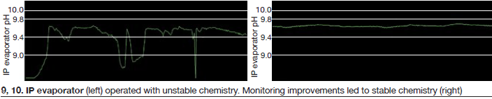
Causes included low sample flows, suboptimal pH analyzers, frequent load changes (impacting conductivity-based dosing), inappropriate alarm set points, and insufficient sample cooling under thermal-shock conditions.
Monitoring improvements included:
- Replaced the solenoid valve in the temperature protection system with a mechanical thermal shutoff valve (TSV).
- Upgraded pH analyzers.
- Improved the instrument maintenance schedule.
- Implemented pH-based trisodium phosphate dosing.
- Verified proper use of sample conditioning components.
- Modified alarm set points to align with new chemistry specification.
- Implemented trim cooling system for sample streams.
The monitoring improvements were conducive the following positive results (Fig 10):
- No nuisance alarms.
- Stable chemistry and dosing.
- Confidence in instrumentation.
Also, the plant implemented various instrument upgrades, modified blowdown procedures, and lowered drum level by about 4 in. Some issues remain such as tiger striping in the LP condenser, and discoloration adjacent to the HP feedwater line into the drum. Work continues.
Reheater tube failure
Luke Mosele, site chemist, and Jason Spencer, operator/maintainer HRSG, NewGen Power, discussed tube failures at the 330-MW Kwinana plant in Western Australia. The 1 × 1 combined cycle has a dual-pressure HRSG with 80 MW of duct firing coupled to a 160-MW steam turbine.
The system includes a seawater-cooled condenser and demineralized water plant (ion exchange).
Investigations into excessive water usage began in February 2016, with tube failures the most probable cause. The plant could not be shut down at the time, and there were no external signs of leakage. Online checks showed a drop in reheater (RH) pressure.
An earlier inspection had found cracks at several header-to-manifold links on the reheater (Fig 11).
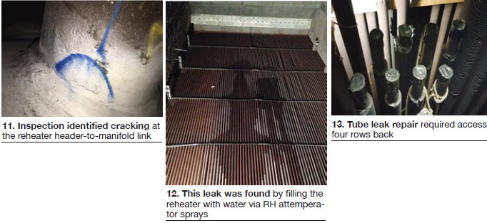
However, a mid-February 2016 force-cooled shutdown inspection found that the leak was not originating from the lower or upper header-to-manifold links. The site then filled the reheater section with water via the RH attemperator sprays, to source the leak (Fig 12).
For commercial reasons the plant was returned to service for three days. Then, it was shut down and scaffolding installed. A leaking tube was found four rows back. Several tubes (eight T23 and four T91) had to be removed (Fig 13).
There were challenges. Contractor experience was minimal. Initial heat-treatment methods were slow. Window welding (versus mirror) was used. The initial time estimate of four days grew into seven. Access was difficult and repair costs were high. Removed tubes were then fully analyzed.
Kwinana returned to cycling service for the next three months. But water usage increased again, and a new test found another leak in a similar location. Commercial operations had to continue until the October outage.
Major cracking was discovered in four tubes, and staff decided to plug the tubes at the headers.
The plant returned to service in November 2016, with 68 thermocouples installed to monitor the operational modes (rapid load changes) which could be causing thermal fatigue. Specialized analyses continue.
Questions and discussion points included fatigue crack location (“odd”), other signs of cracking, modifications that might have an impact, materials, location maps relative to drains and attemperators, duct firing and ramp rates, thermocouple locations, and ability to see duct-burner flames through view ports.
Ongoing investigations include key players such as Quest Integrity Group, Thermal Chemistry Ltd, ALS Consulting LLC, HRST Inc, and Structural Integrity.
New power in the Pilbara
Yarnima Power Station (Fig 14) operates on an island grid in remote Western Australia. Challenges include frequent load variations (both daily and seasonal) and a requirement to maintain minimum spinning reserve. Also, original duct-burner design allowed firing only when the respective GT was above 90% capacity, and the plant rarely operates at this level. Following OEM reviews, new duct-firing options were tested, then reviewed and approved by regulators.
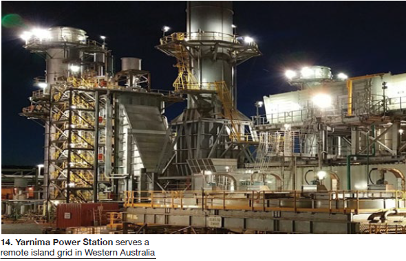
The 190-MW plant supports BHP Billiton Ltd’s current and planned iron-ore operations.
The Yarnima complex, described by Mark Watkinson, principal chemist, TW Power Services, includes:
- Three SGT-800 industrial gas turbines from Siemens.
- Three HRSGs from RCR Energy.
- Two SST-400 industrial steam turbines from Siemens.
- Three black-start diesel/generators.
Newly sunk boreholes supply raw water to the site’s treatment plant and storage tanks. Bore water has high alkalinity and hardness, high silica, and is intermittently contaminated with diesel oil (up to 1 mg/l as TPH, total petroleum hydrocarbons). Also, sources and water quality may change over time or suffer short periods of interruption. Wastewater is routed to two large tanks, then to acid-rock-drainage evaporator ponds.
Water treatment is complex, and no untreated source waters are suitable for cooling-water systems.
Treated permeate is used for cooling-tower makeup and for supply to the GT air-intake evaporative coolers. Cooling-water chemistry is operated at four to six cycles of concentration. Many water issues were identified in the presentation. A project to upgrade online instrumentation is in progress.
HRSG cycle chemistry is:
- AVT(O) for feedwater.
- Emergency dosing of tri-sodium phosphate (TSP) in the HP drum and evaporator.
- OEM oxygen scavenger never used; converted to ammonia dosing at deaerator outlet.
One of three HRSGs often is in layup/standby mode, but must be ready to return to service quickly when needed. Nitrogen capping is used for offline periods of up to four days. Beyond that the HRSG is drained and nitrogen blanketed at a positive pressure above 7 psig (no economizer protection).
Ongoing issues include:
- CO2 pickup from storage tanks.
- Lack of monitoring for degassed conductivity and conductivity after cation exchange (CACE) on all units.
- Corrosion noted in economizers and boiler blowdown.
FAC has not been identified.
In keeping with the risk theme, Watkinson noted that “successful allocation of funds is based on risk profile and sound risk assessment.”
Many questions and helpful ideas followed from the participants—including emergency phosphate dosing, possible pitting from poor layup, membrane biofouling, iron testing, fast-response condenser instrumentation, and flame monitoring.
HRSG designs and trends
Following open-floor discussions to begin Day Two, John Roberts of Jacobs, a global engineering consulting firm, provided a comprehensive overview of HRSG design improvements and trends, touching on the major global OEM suppliers.
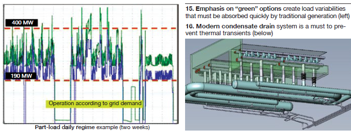
Many trends are driven by the global emphasis on green options, creating variabilities in load that must be absorbed quickly by traditional power (Fig 15). Fluctuating gas prices add to the uncertainty.
Fast starts and flexibility carry the weight; combined cycles are becoming “mid-merit” vehicles to meet demand. HRSG designers must therefore address:
- Faster ramp rates to match green-power unavailability.
- Ongoing demand for higher efficiency and lower emissions.
- Lower capital and lifetime maintenance costs.
- High reliability under all operating regimes.
Primary design issues: “One of the earliest problems faced by HRSG designers,” stated Roberts, “was large volumes of condensate.” This requires good drains (Fig 16) and correct drain operation to prevent thermal transients.
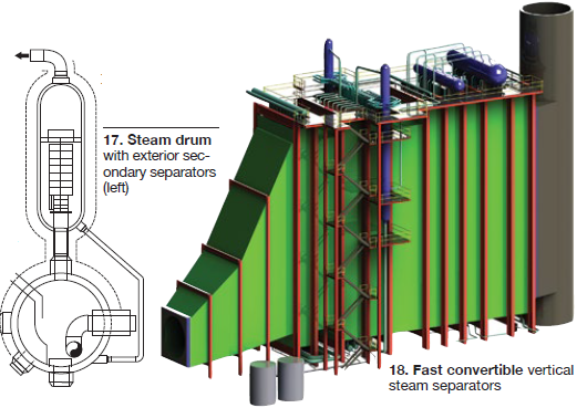
He continued, “The steam drum is seen by many as the limiting factor to a fast start,” because of problems caused by the differential temperatures (steam and cold feed). For this, OEM designers are offering two solutions: a patented DrumPlus™ design by NEM with secondary separators outside the drum (Fig 17), and vertical steam separators by Babcock & Wilcox (Fig 18). Single-row harp designs also were discussed.
Materials also remain a common issue. Criteria for progress include:
- Materials with greater allowable stress at high temperature and pressure.
- Properties of thermal conductivity and thermal expansion.
- Grain structure and heat treatment.
- Weldability and transitions.
These items were reviewed and discussed.
Almost unanimously, OEMs are recommending and offering online real-time monitoring programs for critical components (drums, high-temperature headers, etc). Specific commercially available examples were given.
For superior efficiency, there is a possible move toward supercritical once-through (Benson-type) units, but design benefits and limitations must be carefully explored. Also in development mode is reduced backend temperature for more heat/energy extraction (stack temperature of perhaps 160F). Discharge corrosion issues are also under investigation.
Material damage tolerance and codes
Traditionally, the ASME Boiler and Pressure Vessel Code uses mechanical strength as its primary basis for construction rules. Other material considerations stem from recognized material specifications (ASTM, for example). Yet with more moves toward critical service (higher temperatures and pressures, and cycling), the current Code approach may be limited. Perhaps damage tolerance needs to be part of the Code.
Mike Drew, Australian Nuclear Science and Technology Organisation (Ansto), first addressed this topic by looking back to a 1983 main-steam piping failure at Philadelphia Electric Co’s Eddystone Unit 1.
Eddystone (325 MW) was the world’s first truly ultra-supercritical coal-fired utility boiler, and when built in 1960 was the most efficient coal-fired plant in the world. It is now listed by ASME as an “Historic Mechanical Engineering Landmark.”
Original steam outlet parameters were 1210F and 5000 psig; temperature later was reduced and was held at 1135F until unit retirement in 2014.
A steam-pipe failure occurred after 130,000 hours of operation; and there were no indications that the leak might develop. Failure analysis showed intergranular cracking; extensive creep-induced cavitation was observed at grain boundaries in damage areas, with sigma damage (a loss of fracture toughness caused by exposure to high temperature) but no evidence of swelling. Piping material met the specification requirements (both mechanical properties and chemistry).
Cracking was directly related to residual stress induced by thermal shock events (condensate flow) during shutdowns. The material’s ability to tolerate abnormal operating stresses was compromised.
For the replacement piping, primary emphasis was on chemical composition control to improve the material’s damage tolerance—specifically:
- P91. EPRI recommends more restrictive compositional controls for P91 material. The example given was a P91 header failure in the UK at 60,000 hours, and high variability in ductility within the header. The EPRI specifications are now much tighter than the original for SA-335 P91. Examples were given showing differences in both strength and rupture ductility at different temperatures.
- TP304H and TP347H. The National Institute for Materials Science (NIMS) has evaluated creep-life variability factors for its Creep Data Sheet Project. Studies were conducted up to 200,000 hours. Drew presented data on the long-term effects of nitrogen and boron on material properties at high temperatures.
The bottom line: Damage tolerance should be incorporated into design. Damage tolerant means that a material can uniformly incorporate damage and will normally show signs of distress (during inspections) prior to failure. Damage intolerant means that there is localized accumulation of damage or strain, often at grain boundaries.
Drew offered the following recommendations:
- 1. Critical service should be defined for each construction code, with failure of a pressure part defined as one that would threaten personnel safety and/or result in extended downtime.
- 2. For critical service, a damage-tolerant material should be required, or if a damage-intolerant material is used, a penalty factor on allowable stress should be imposed.
- 3. For grades of materials in the power industry, codes should be updated to define a damage-tolerant class for a given alloy, perhaps labeled the DT Class. This can be added to ASTM requirements as supplementary.
Update on cycle chemistry
Chairman Dooley then presented an update on HRSG cycle chemistry and FAC. “The base issues are global,” he said, “and many plants are experiencing repeat failures.”
Repeat failure situations include:
- Corrosion product transport.
- HP evaporator deposits.
- Instrumentation (insufficient).
- Drum carryover.
- Shutdown protection (inadequate).
- Contaminant ingress.
- Failure to challenge the plant’s chemistry status quo.
Dooley has analyzed data from 70 worldwide HRSG assessments and 114 fossil plant assessments. He knows this stuff.
Steam-turbine PTZ damage and failure
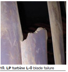 A case study covered a 675-MW 2 × 1 combined cycle equipped with a triple-pressure reheat HRSG. A failure in the phase transition zone (PTZ) occurred at 95,000 hours. Cycle chemistry was an amine blend with reducing agent, and phosphate to all drums. There were multiple leaks in the titanium condenser tubes.
The LP turbine experienced an L-0 blade failure (Fig 19) and pitting was extensive (transition from pit to micro-crack to failure).
Seven root-cause chemistry situations were identified (five directly related to PTZ damage):
- 1. Total-iron corrosion products not measured.
- 2. No HP evaporator tubes removed to assess deposits.
- 3. Instrumentation at low level (53%) compared to recommendations in technical guidance documents issued by the International Association for the Properties of Water and Steam (IAPWS). Visit http://www.iapws.org/.
- 4. Drum carryover not measured.
- 5. Shutdown protection (DHA) not applied.
- 6. Repetitive contaminant ingress.
- 7. Status quo on plant guidance and action levels.
Avoiding repeat situations is critical, explained Dooley:
“Cycle-chemistry-influenced failure and damage always can be related back to multiples of repeat cycle-chemistry situations in fossil and combined-cycle plants.”
Thermal assessments
This was followed by an update on thermal assessments by Robert Anderson, principal, Competitive Power Resources, a Florida-based consultancy, and a member of the AHUG steering committee.
First step in a thermal assessment, he said, is to review HRSG design and component configurations. Primary dangers, well understood, are:
- Drain pipes too small.
- Blowdown tank above the HRSG’s headers.
- Attemperator leakage or overspray.
- Drain pipes not having continuous downward flow.
- Drain operation not based on reliable condensate detection.
Plant DCS data can help identify condensate migration, RH and superheater (SH) overspray conditions, and HP pressure ramps set too high during startup. The data, however, must be reviewed carefully.
Operating choices are also important:
- Are drains opened during purges?
- Is there manual manipulation of outlet steam-temperature set points?
- Is a routine attemperator inspection program in place?
- Is a tube-failure root-cause program in use?
Participants then discussed drum thickness and ramp rates.
Economizer tube failure
Anita Zunker of PEI Pressure Equipment Integrity explained a recent HP economizer tube failure at the Stratford combined-cycle power station at Taranaki, New Zealand. Commissioned in 1999, the plant was in baseload service until moving to more flexible operation in 2013, with extended out-of-service periods. “Robust preservation procedures are in place,” stated Zunker.
Current out-of-service programs include:
- Short term (few days only): wet storage.
- Longer term: nitrogen capped, drained hot, piping dehumidified.
The tube leak was detected at the end of March 2016. The pinhole leak occurred in HP economizer 7, top tube-to-header weld (sixth tube from east end). Material is carbon steel.
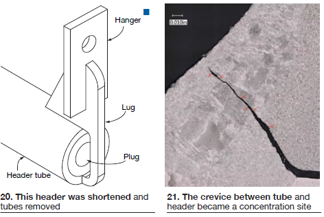
The repair method: Six tubes were demolished and the header was cut shorter (Fig 20).
A pressure test then found another leak (seventh tube from west end). That leak was plugged, and metallurgical analysis of the first leak showed oxide-filled cracks and corrosion on both tube and header surfaces (within crevice), along with minor pitting of the internal tube surface.
The cause was a corrosion fatigue crack, with the crevice between tube and header acting as a concentration site for corrodents, and as a stress riser (Fig 21).
Data from 2006 also were reviewed. The conclusion: original welding defects are an influence.
And the solution: Concentrate on what can be controlled. Maintain operating and preservation procedures to the highest standards to minimize ongoing risks. Be aware of the issues.
Online analysis of ultra-trace iron, copper
Tomi Maatta, ANZ-based MEP Instruments, addressed online analyzers for what he called “ultra-trace” iron and copper. The purpose: To understand the correlations between operating conditions, FAC, and metals transport.
This presentation of a promising new technology discussed separation of dissolved and particulate metals, voltammetrics, and repeatability of results.
Also discussed in detail were sampling points, analyzer layout, and detailed online test results. Corrosion examples also were shown.
Outage activities at Te Rapa
On Day One, Contact Energy discussed extending inspection periods at various plants—including Te Rapa in New Zealand (refer back to Fig 1). Rachelle Meijer, Contact Energy, was at the podium on Day Two to discuss current outage activities at the plant.
A full external inspection had been conducted before the last outage. Hot spots were found around the diverter door and transition duct. A follow-up comprehensive internal inspection included hardness and dye-penetrant testing of superheater tubes. Findings were:
- Duct liner plate buckling.
- Duct burner 2 (of 12) had sagged; DB 3 was beginning to sag.
- Duct-burner final elbows found highly corroded.
Soon after restart, water usage increased and IP steam production decreased. Shutdown followed. A leak was found between the economizer and evaporator headers. Tube samples were sent to Structural Integrity, identifying corrosion fatigue.
Contributing factors were:
- Thermal shocking during non-optimal trip test.
- Poor layup and storage in past.
- Poor design of header and tube attachments.
Moving forward, actions will include:
- Conduct further inspections at next outage.
- Install thermocouples and strain gauges.
- Install nitrogen generator for layup.
- Update procedures for trip testing.
- Improve mass balance data.
Various participant questions and constructive ideas followed.
Ultrasonic control of SH/RH drains
Anderson returned to the podium and presented on ultrasonic control of SH and RH drains.
Major amounts of condensate form in SH and RH tubes during pressurized startup, he said, and drain flow varies greatly with pressure. Small transients are noticeable in bulk steam, but at the tube level these transients (stresses) are very large. The solution is optimum drain operation.
One requirement is to detect water to minimize steam release during purge. Thermocouples cannot do this; high-flow drain-pot arrangements can, but they are expensive and will not fit (physically) under many existing HRSGs.
Ultrasonic detection can determine water in drain pipes, using the transit-time technique, but must be adaptable to high temperatures. Such a design, the WaveInjector®, was reviewed in detail (Fig 22).
This is now installed on four different HRSGs for testing—various drain-pipe sizes, different materials, and various pipe configurations and control-valve types. Anderson said that “once installed, the WaveInjector is very reliable,” but performance can be impacted by many variables. Testing continues.
Guidelines for cycle chemistry
David Addison, principal, Thermal Chemistry, and a member of the AHUG steering committee, followed with proper application of IAPWS guidelines for effective cycle chemistry. “Effective cycle chemistry minimizes deposition and corrosion within the whole water/steam circuit of a CCGT plant,” Addison stated. “But it must be a continuous process.”
 With that introduction, he reviewed the common results of poor chemistry, including the following:
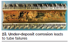
- Evaporator iron oxide deposits.
- Under-deposit corrosion and tube failures (Fig 23).
- Mechanical and vaporous carryover.
- Deposition in superheaters and reheaters.
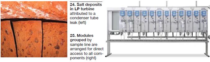
For the steam turbine, this also means:
- Deposits (Fig 24).
- Pitting and cracking.
“However,” Addison warned, “cycle chemistry often is overlooked, carried out incorrectly, or not carried out at all.” Such issues often lead to both equipment failure and plant personnel safety concerns. They can present high-risk situations.
Addison also pointed to a problem not often considered: “A unit is designed in country A, manufactured in country B, built in country C, and uses specifications and guidelines from country D.” Therefore, “the world now needs truly international guidance on cycle chemistry that can be the foundation for guidelines in each country, and for manufacturers and other organizations worldwide.”
IAPWS is uniquely placed to offer such guidance, with active participation by knowledgeable representatives from nearly two-dozen nations and drawing on the resources of several international standards-setting organizations—EPRI, VGB, ASME, and others. The IAPWS TGD process is comprehensive, specific, and robust, with an extensive technical review component.
Addison then reviewed several examples, ending with two that were new for 2016:
- HRSG HP-evaporator sampling for internal-deposit identification and determining the need to chemically clean, and
- Application of film-forming amines in fossil, combined-cycle, and biomass powerplants.
He then outlined the following optimization path for cycle chemistry:
- 1. Understand your current feedwater and evaporator cycle-chemistry program.
- 2. Understand your HRSG design and materials.
- 3. Determine current details of sample points and analyzers, dosing systems, carryover testing, corrosion product sampling, and failure history.
- 4. Access IAPWS TGDs at www.iapws.org.
- 5. Select your feedwater program via volatile treatment TGD process.
- 6. Select your evaporator program via volatile treatment and solid alkali TGD selection process.
- 7. Apply customization according to the TGDs.
- 8. Review your analysis system against the instrumentation TGD.
- 9. Review carryover testing and steam chemistry according to TGDs.
- 10. Begin corrosion-product sampling and benchmark feedwater and evaporator total iron levels.
- 11. Undertake routine tube sampling and analysis.
- 12. Ensure proper layup and storage practices.
- 13. Ensure chemical dosing is automated and working.
- 14. During shutdowns, ensure specific cycle-chemistry inspections are completed and documented.
- 15. Review operating chemistry data at least annually.
- 16. Watch for new TGDs.
IAPWS updates
Dooley followed Addison to explain both the TGD process and the various IAPWS technical groups—including the Power Cycle Chemistry Group—and offered an overview of current activities of the Australian National Association.
He also listed and outlined future possible TGDs:
- Ensuring the integrity and reliability of demineralized makeup water supply to the unit cycle (2017).
- Neutralizing amines (2017).
- Film-forming products for nuclear plants (2017).
- Air in-leakage (2017).
- Steam chemistry for geothermal plants (white paper 2017).
- Corrosion products in flexible (cycling) plants (white paper 2017) .
Steam/water analysis
Chris Wellard, Swan Australia, ended the day with a review of outdated versus modern sampling and analysis designs.
The fundamental instrumentation differences:
- Component-oriented design (dry rack/wet rack), or
- Modular process-oriented design—online instruments featuring integrated sample preparation (degassed cation conductivity, cation conductivity).
With changes to plant operations (flexibility), new components, and changes to original water chemistry details and methods, traditional systems are no longer adapted to actual monitoring requirements. Even in some new plants, outdated dry/wet-type rack/panel arrangements can prevail, in part to reduce capital cost.
But there are consequences:
- High O&M costs.
- Upgrade or modification difficulty.
- Low reliability.
- Collateral damage to plant components.
The new modular Steam/Water Analysis System (SWAS) is driven by both process and function; modules can be grouped by sample line for:
- Improved O&M (less cost).
- Upgrades/modifications.
- Instrumentation giving perspectives on the process (Fig 25).
Discussions then centered on conductivity measurement and degassing devices. “Swan’s position,” stated Wellard, “is that the fully controlled thermal degasses system, with automatic boiling control, is the optimal method.”
Examples of upgrades and replacement systems were then discussed.
Workshops
Three workshops were held on the third day:
- 1. Attemperator issues.
- 2. Preparation of a covered pipe system management plan.
- 3. Anatomy of HRSG thermal surveys.
Submitted questions
Technical questions submitted by participants before the event were discussed periodically during the meeting, both through the presentations and during open-discussion periods. Selected questions included:
HRSG O&M
- Risk-based inspection process.
- Spray water control (automatic and manual bypass).
- Low-load operation strategies.
- HP bypass on startup.
-
- To save treated water.
- To mitigate pressure-control-valve corrosion.
-
- Corrosion under insulation.
Cycle chemistry
- Long-term dry storage options.
- Corrosion-product sampling.
- Phosphate dosing-line issues. CCJ
