
There were three breakout sessions on the afternoon of GE Day at the 25th annual 7EA Users Group meeting, Nov 1-3, 2016, in Hershey, Pa. CCJ editors attended the combined-cycle workshop, which offered presentations and discussion on heat-recovery steam generators, steam turbines, generators, and control systems.
Michelle York, an HRSG application engineer who came to GE when it acquired Alstom, wanted to focus her comments on topics of greatest interest to the 20 or so users in attendance so she asked them where they were suffering the most pain in their HRSGs and steam systems.
To get the discussion flowing, York put up a list of common issues which included the following: deterioration of tube restraints, flow-accelerated corrosion, removal of gas-side deposits, the life of pressure parts, duct-burner maintenance, and attemperator failures. Everything on her list got a lukewarm response except for the last item. Attemperators were the near-unanimous source of pain at the plants represented.
The editors thought this surprising. CCJ’s coverage of attemperator issues goes back to the first issue, published in fall 2003. “Steam-turbine bypass systems” was co-authored by Robert W Anderson, then manager of combined-cycle services for Progress Energy Inc, and Henk van Ballegooyen, then president of Gryphon International Engineering Services Inc (now CHA Engineering Service), a Canadian consulting firm.
On the road to the quarterly’s 50th issue—the one you are reading—attemperators have been featured in many articles. It’s probably safe to say that CCJ has published more editorial pages on attemperators over the last 13 years than any other periodical serving the generation sector of the electric power industry.
And Anderson, now an HRSG/steam-system consultant and member of the magazine’s Editorial Advisory Board, has had a hand in several. You can access many CCJ articles contributing to the industry’s collective knowledge on attemperators by using the keyword search function at the top of this page.
The editors called Anderson shortly after the 7EA conference to ask why attemperators continue to be a problem, what is being done to mitigate the issues, possible new designs on the drawing board, etc. The first thing he said was “Attend the first annual ‘HRSG Forum with Bob Anderson,’ Feb 28-Mar 2, 2017, in Charlotte. Problem-free steam attemperation is one of the hot topics on the discussion program.”
Commercial complete, Anderson got down to business and commented on the informal survey conducted by York in Hershey. In today’s post-regulated industry, he said, no comprehensive database exists to quantify which HRSG system or equipment causes plant operators the most problems. Anderson’s experience based on review of owners’ operating data, and from listening to users at various HRSG conferences worldwide, suggests that inter-stage and terminal attemperators are at the top the list.
During the late 1990s and early 2000s, the “bubble” years, he continued, many of the HRSGs supplied for F-class combined cycles were equipped with an attemperator in which the spray-control-valve trim was located inside a “mast” or “probe” that extended into the steam flow path (figure).
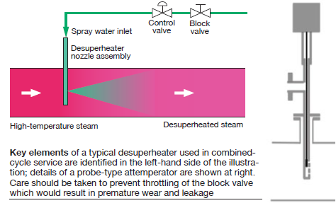
The probe-type attemperator works this way: The valve trim moves up and down inside the mast, sequentially turning on or off individual spray nozzles. Note that this arrangement uses fixed-area orifices as nozzles, as the detail in the figure illustrates. It provides the relatively wide range of spray-water flows required at a competitive price. However, exposing the moving parts of the close-tolerance valve trim to thermal cycles—heat soaking in the steam pipe when not spraying and thermal quenching when spraying begins—caused erratic trim movement, cracking of the nozzle assembly, and, in the extreme, liberation of the nozzle assembly.
When the nozzle assembly fractures or liberates, water impinges on the inside wall of the steam pipe. A typical result is cracking on the internal surface of the pipe and of girth welds.
Anderson said his findings on consulting assignments, comments from owners at user-group conferences, and discussions with boiler and attemperator manufacturers suggest that most “internal-trim” attemperators in F-class combined cycles have been replaced with more reliable equipment and have not been installed in new HRSGs for several years.
Good news, correct? No; at least not in Anderson’s experience. You might think the frequency of attemperator-related failures would decrease as better equipment is installed, he said, but that does not seem to be the case.
Thermal transients. Anderson went on, “Barry Dooley [a senior associate at Structural Integrity Associates Inc] and I conduct what we call Level I HRSG surveys. These one-day asset examinations focus on identifying damaging thermal transients, evaluating the effectiveness of the plant’s cycle chemistry program, and determining in which locations with the HRSG flow-accelerated corrosion (FAC) may be active.
“A key means of identifying undesirable thermal transients during these surveys is an informed review of historical operating data. Very few operational errors—or poor performance of key systems like superheater drains, attemperators, steam-turbine bypass systems, etc—result in immediate equipment failure.
“Rather, most operational errors or oversights produce transients that cause accelerated incremental accumulation of thermal-fatigue damage. If the transient is repeated often enough, failure will occur. If you know what to look for, evidence of these transients can be found in the plant’s historian and corrective actions taken to mitigate or eliminate additional damage.”
Anderson said that he and Dooley have conducted more than 50 thermal-transient surveys on HRSGs supplied by 16 different manufacturers and incorporating many different models of attemperators. “Along the way,” the consultant said, “I’ve formed some opinions about attemperator problems, what causes them, and how to avoid them.”
Causes include one or more of the following (in combination):
- Insufficient maintenance.
- Ineffective control logic.
- Leaking spray water.
- Overspray
- Defective hardware (nozzles, thermal liner, valves).
- Defective design (straight run of steam pipe upstream and downstream of the attemperator too short, no steam pipe drain or ineffective drain, inferior hardware).
Attemperators operate in very severe thermal and differential-pressure environments. Even the best hardware requires routine inspection to identify and replace worn or broken components before they damage steam pipes, headers, and tubes. Of the more than 50 plants Anderson and Dooley have surveyed, only one-fifth have a routine attemperator inspection program in place, leaving plenty of room for inexpensive improvement.
Rapid and large changes in gas-turbine exhaust temperature during startup, and high exhaust temperature characteristic of low-load operation, can make it difficult for the attemperator to maintain superheater/reheater outlet steam temperatures within design limits and also avoid overspray conditions. Many HRSGs built during the “bubble” used a simple feedback loop for steam-temperature control, resulting in poor attemperator performance.
This encouraged some operators to manually manipulate the attemperator set point, often causing severe overspray conditions. The use of well-tuned cascade control logic can achieve acceptable automatic attemperator performance for most HRSGs without operator manipulation.
If spray water leaks from the attemperator nozzle during periods when steam flow is low, or zero, it will fall onto the internal surface of the steam pipe and cause thermal-quench damage, and significantly increase the quantity of water that must be drained during the next startup.
Anderson says he often sees evidence of leaking during a review of operating data. “Sometimes the cause is insufficient inspection/repair of the block valve, but mostly it’s due to the use of master control valve/ martyr block valve control logic. In my view, it’s not possible or necessary to maintain tight shutoff at the control-valve seat if the block valve maintains long-term tight shutoff.
“Master control valve/martyr block valve logic causes many unnecessary block-valve open/close cycles and virtually ensures both valves will leak after only a few runs. You can prevent leakage by arranging the logic to open the block valve only once during startup—when exhaust temperature increases to around 950F—and to close only when the exhaust temperature decreases below 950F during shutdown.”
Overspray occurs when more water is injected into the steam than can be evaporated before reaching the thermocouple located downstream of the attemperator. If the steam temperature downstream of the attemperator decreases to within 30 deg F of saturation, damage to pipes, headers, and tubes may result. Control logic should be arranged to prevent the control valve from opening any further when this overspray limit is reached.
Most attemperators in use today use spring-loaded variable-area spray nozzles which provide good atomization over a wide range of flows; however, they depend on free movement of a poppet to work properly. Oxidation of the poppet stem or guide and fouling by debris in the spray water can cause nozzles to stick open or closed.
Attemperator manufacturers have worked to eliminate oxidation issues by changing materials. Most now recommend installation of a strainer upstream of the block valve to prevent valve and nozzle fouling. Routine inspection of nozzles is important. When in doubt about a nozzle’s condition, replace it with a new one and send the suspect nozzle to the manufacture for refurbishment.
Thermal liner. Most desuperheating stations also incorporate a thermal liner to protect the steam pipe from spray-water impingement. But liners can crack, warp, or slide down the steam pipe, making routine inspection important. Lesson learned: Small cracks might be monitored via frequent inspections, but if left too long may result in liberation of parts, or all, of the liner, disrupting steam distribution to downstream heating surfaces or risking FOD to the steam turbine if from a terminal attemperator.
A few units suffer from attemperator steam pipes that are too short to permit spray water to evaporate before it impinges on downstream pipework. In some cases, the pipe may be just long enough that replacing the existing attemperator with one that produces better atomization, hence faster evaporation, may solve the problem. In severe cases the pipe must be made longer. CCJ