Silverhawk Generating Station underwent a period in which the safety valve for the plant’s auxiliary steam system failed repeatedly, NV Energy engineers Rishi Velkar and Frank Romans told the editors. Consequences of the failures included frequent valve replacement and loss of production through forced outages.
Examination of the failed safety valves revealed seating-surface erosion associated with high-velocity steam flow. Historical process data (Fig 1) showed transitional phases where the auxiliary-steam pressure would breakdown into uncontrollable oscillations. Testimonials from plant operators conveyed the only means to stop the oscillations was through manual intervention.
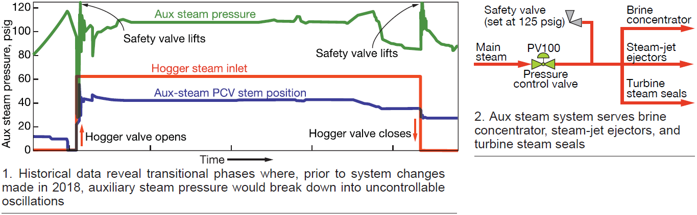
During the course of startup, the auxiliary-steam control valve PV100 (Fig 2) is required to maintain constant downstream pressure with a supply pressure that varies from 110 to 1600 psig. Concurrently, operation of the condenser air ejector (hogger) introduces practically an “all-or-nothing” demand on the aux steam system.
A varying main-steam supply pressure, combined with extreme changes in demand, apparently caused the oscillations and subsequent safety-valve failures.
Comparison of the Silverhawk auxiliary steam system to arrangements used at other plants highlight a stark difference. Most others use two steam sources to supply the auxiliary steam system: main steam and reheat steam. Each has a control valve to regulate downstream auxiliary steam pressure.
The advantage of the two-source scheme: Auxiliary-steam control valves regulate downstream pressure for a much lower range of supply pressures. Thus, they are less likely to break down into oscillations.
Installation of a system similar to that used successfully by others is a possible long-term solution. For the immediate need, any solution had to incorporate existing equipment.
Solutions. Here’s what was done:
1. Modified the control-system program so the auxiliary-steam-pressure control algorithms used variable proportional and integral values.
Prior to this change, the proportional and integral values were constant. Now, these values change as the main-steam supply pressure varies. Deploying this strategy made the pressure-control response appropriate for a given supply pressure.
2. Changed the control scheme to mitigate the impact of “all or nothing” demand on the auxiliary steam system.
When hogging begins, the demand for auxiliary steam increases rapidly and steam pressure drops below that required for proper operation. Conversely, when the hogger is removed from service, the demand for aux steam drops to zero and its pressure spikes, typically causing the safety valve to open.
Changes to the control scheme comprised feedforward signals that adjust the steam-pressure regulator valve whenever the hogger is placed in, or removed from, service. Automatic changes to the aux steam pressure setpoint also occur.
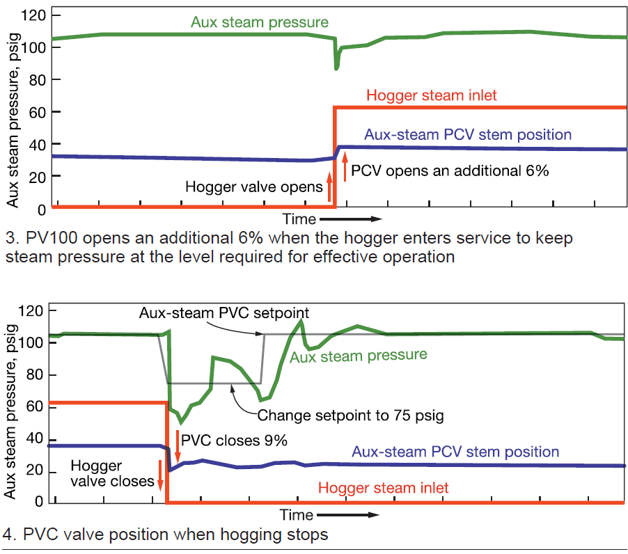
Once the hogger begins operating, the regulator valve (PV100) opens an additional 6% to keep pressure at an effective level; the auxiliary-steam pressure set point stays at 105 psig (Fig 3).
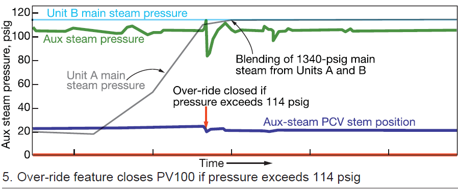
Whenever hogging stops, the regulator valve (PV100) closes an additional 9% to limit the pressure increase. Simultaneously, the pressure setpoint drops to 75 psig. The lower setpoint holds for a period of 10 minutes. The 10-min hold assures the pressure stabilizes before the automatic return to the normal setpoint of 105 psig (Fig 4).
3. The aux steam system must function throughout a variety of dynamic operating conditions. Obviously, the hogger is most critical, but other scenarios can upset the system as well. Installation of an “override” control scheme reduced sporadic opening of the safety valve.
The override activates when aux steam pressure exceeds 114 psig. While the override is active, the regulator valve (PV100) closes a percentage that is proportional to the rise of steam pressure above 114 psig. More specifically, an aux steam pressure slightly above 114 psig will result a small percentage of regulator-valve closing; a pressure significantly above 114 psig produces a higher percentage of valve closing (Fig 5).
4. The company’s engineering team reviewed the aux steam piping system, concluding that the safety-valve setting was conservative and most likely determined during plant commissioning. The team decided to raise the safety setting to 140 psig, which allows a larger margin of operation.
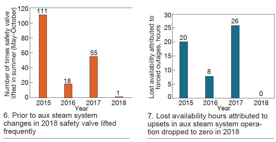
Results. Since implementation and tuning of the 2018 solutions summarized above, there have been no safety-valve failures or loss of production hours (Figs 6 and 7). Additionally, the safety valve opened only once, in May, and a minor tuning change corrected the issue. Afterwards, the safety valve did not open again for the remainder of 2018.