

Procedure reduces post-outage recovery time, minimizes pitfalls on restart
Challenge. Plant management was not happy with the length of time it was taking to recover from extended outages, or with the pitfalls often encountered during the first start after an outage. These included missing the proper equipment line-ups and doing an average job of leak-checking, among others.
Plant’s goals were to maximize availability and improve post-outage first-start reliability. Since major outages occur infrequently, senior personnel wanted to develop a formal procedure; relying on memory is inadequate for ensuring staff is following the proper sequence and not missing line-ups, etc.
Solution. Management assembled a team to develop the Major Outage Recovery Procedure presented in the sidebar. This checklist provides the steps necessary to take the plant smoothly from the “LOTOed” condition at the end of the outage through the first start. It follows a logical sequence and includes such items as these:
- Specific line-ups based on post-outage equipment conditions. Example: “If the cooling tower is drained, leave the process and sparging steam isolation valves closed.”
- Specific equipment checks, based on outage work performed. Example: “Perform fuel-oil tubing leak checks if gas-turbine combustor work was performed.”
- Transitioning from temporary equipment cooling back to auxiliary cooling water (ACW).
- Establishing proper chemistry control for initial fills of the cooling tower and HRSGs.
- Tracking, minimizing, and/or eliminating abnormal conditions—such as line-ups—throughout the procedure.
The team agreed that the procedure would be a “living document” –one improved and updated from outage to outage.
Precautions:
- Consider the Operational Checklist as a guideline that likely will require modifications to customize for your plant. The baseline procedure you develop should be reviewed before each use as it also may need modifications depending on end-of-outage conditions, equipment out of service, etc. Specific items not applicable for a given restart should be lined out.
- Wear appropriate PPE and follow applicable Material Safety Data Sheets when venting chemical feed pumps.
- Important: If any of the air-operated GT fuel-gas valves were worked on during the outage, keep the manual isolation valve upstream of the OST closed until the applicable valves are calibrated and stroked. Note this on the “Abnormal Conditions Sheet” that you should have as an addendum to the checklist.
- Check and resolve the Abnormal Conditions Sheet throughout the procedure.
- Add special instructions as applicable.
Results. The team developed the initial draft of the Operational Checklist in the middle of the 2014 combustion inspection (CI) and implemented it at the end of the outage. Plant has since used the checklist after every extended outage, including the 2015 major inspection and 2016 BOP outages. Staff continues to improve the checklist whenever a gap in the procedures is noticed.
Plant operators and management agree on the following benefits of the effort:
- Much less confusion over “what do next” with regard to equipment restoration, line-ups, etc.
- Faster restoration of proper cooling-tower and HRSG chemistry thanks to specific procedural steps for initial chemical dosage and hotwell pH correction.
- Noticeably fewer piping and equipment line-ups found out of position.
- Gas leak checks, gas flow testing, and fuel-oil tubing leak checks—all referenced in the procedure—were properly performed in logically ordered sequence following the CI.
- Since implementation of the procedure, plant has not experienced a delay or equipment protective action caused by a missed line-up, abnormal condition, or other post-outage oversight.
Project participants:
Randy Culler, lead operator
All control-room operators
Dan Tesch, maintenance supervisor
Mark Barrett, operations supervisor
OPERATIONAL CHECKLIST of activities to perform prior to first start after an extended outage
Note: Steps may be done concurrently or out of order. Initial each step performed; if a particular step is not applicable, mark it N/A.
- 1. Ensure the gas-turbine CO2 fire-protection root valve is tagged closed for any non-line opening/non-CSE/non-hot work being conducted in the GT mechanical package.
- 2. If/when conditions allow, enable the GT lube-oil heater. Oil temperature must be above 70F to start a LO pump.
- 3. Once cooling-tower work is complete, clear the cooling-tower LOTO.
- 4. Fill the cooling tower.
- 5. Start a main circulating-water pump when the tower level is higher than 40 inches.
- 6. Once chemical feed pumps are vented, start one and dose the tower at 100% output for nine hours. This will give near the 17-gal requirement to treat the initial fill of water. Continue dosing the tower until the dioxido(dioxo)molybdenum tracer is in-spec.
- 7. Line up the ACW pumps and system as applicable. Vent the pumps and suction strainers.
- 8. Start an ACW pump.
- 9. Line up the following loads to ACW (includes swapping from temporary cooling), as applicable:
- GT lube-oil cooler, vent the water side.
- Steam-turbine (ST) lube-oil coolers, vent the water sides.
- GT control oil.
- ST electrohydraulic control-oil skid.
- Air-compressor aftercooler.
- Auxiliary-boiler blowdown tank.
- Vent GT hydrogen cooler if necessary.
- 10. Line-up raw-water cooling to the sample panel, including the recirc skid and outlet to ACW.
- 11. Feed phosphoric acid to the ACW system at 100% output for 12 hours. Test for orthophosphate and continue dosing until in-spec. See priming instructions on the back of the five-function valve. Circulate with a circ-water and ACW pump until chemistry is in-spec. The circ-water pump then may be secured.
- 12. Start up the ST lube oil system and place the unit on turning gear (TG). This may be done earlier if raw water is hosed up to the LO coolers. Line-up the LO vapor extractor, LO pump, and dehumidifier. Note, that the LO temperature must be above 50F prior to starting a lube-oil pump and over 70F prior to putting the machine on TG.
- 13. Once ST work is complete, start up the steamer’s electrohydraulic oil system.
- 14. Once GT work is complete or conditions allow, clear the CI/HGP (combustion inspection/hot gas path) LOTO, start a lube-oil pump, and place the GT on turning gear. This may be done earlier if raw water cooling is hosed up to the lube oil cooler. Note that LO temp should be above 80F before putting the engine on turning gear.
- 15. Once GT work is complete or conditions allow, start up the control oil system.
- 16. Perform the critical-valve stroke checklist as early as conditions allow.
- 17. Once HRSG steam and waterside work is complete, clear the HRSG waterside LOTO.
- 18. If the GT generator was purged to air, pressurize/swap to CO2, then to hydrogen. Perform a generator air test, if needed, prior to purging to CO2.
- 19. Verify the GT generator hydrogen-purity blower is operating and purity is 95% – 99%. (A 100% indication indicates a problem with the blower.)
- 20. Pressurize the fuel-gas heater.
- 21. Leak-check applicable portions of the fuel-gas piping if work was performed during the outage.
- 22. Spark-check GT igniters.
- 23. Once the CT Exhaust and HRSG are closed up, clear HRSG fireside LOTO.
- 24. Perform DCS point search. Re-enable alarm and limit checks. Place off-scan points back on scan.
- 25. Fill the hotwell and vent the condensate pumps.
- 26. Start a condensate pump and establish normal recirculation through the condensate storage tank. Start the condensate amine pump and raise hotwell pH to 9.6.
- 27. Prepare for filling the HRSGs by performing the following:
- Confirm/verify that all evaporator and economizer drains valves are closed.
- Check superheater drains are throttled open and lined up to the blowdown sump.
- Check balance-of-plant (BOP) drains open.
- Check drum vents open.
- Check steam stops and non-return valves open.
- 28. Once Hotwell pH is established, fill HRSG drums, in accordance with the “Filling Drums after HRSG Work Operational Summary.” Vent boiler feed pumps if they, or associated piping, were drained.
- 29. Crack open sparging steam to the HRSG evaporators. As the drum temperatures warm, the sparging steam may be opened up more.
- 30. Shut HRSG drum vents once the applicable drum pressure reaches 15 psig.
- 31. Check and resolve the Abnormal Conditions Sheet as applicable.
- 32. Fuel-oil leak check/transfer preparations: If fuel-oil tubing leak checks are necessary, line up the water injection skid the night or day before leak checks are scheduled to begin, in accordance with applicable documentation. If a fuel-oil transfer test is necessary, conduct the OEM’s suggested pre-start procedures the day before the test and flush the flow divider.
- 33. Perform gas-flow testing and leak checks in accordance with “Gas Flow Test After GT Work Operational Summary,” if needed. Prerequisites: Install jumpers and LOTO the GT igniter breaker. Run all GT enclosure fans and turn on sufficient generation-bay roof ventilation fans to handle any natural-gas leakage from the turbine. Finally open generation-bay doors to maximize air exchange.
- 34. At the conclusion of gas flow testing, perform fuel-oil tubing leak checks if desired. Plus:
- Return GT enclosure fans to auto.
- Nitrogen-purge the combustion dynamics monitoring system.
- 35. Perform a “dummy start,” if needed, with igniters powered off.
- 36. Perform an actual test start, if needed.
- 37. On the first start, after the outage, perform the following:
- Put enclosure fans into “manual.”
- Turn on enough generation-bay roof fans to handle the “burn off” of anti-seize products.
- Open generation-bay doors to maximize air exchange.
- Confirm all cooling-tower chemical feeds are pumping.
- If fuel-oil tubing leak checks were performed, perform “A-” and “B-” stage water purges, watching for flashbacks to verify “A” and “B” fuel tubing is properly connected.
- 38. Perform a fuel-oil transfer test, if needed.
- 39. Secure and lay-up the water injection skid, once fuel-oil tubing leak checks and the test transfer are complete.
New LOTO qualification program results in zero violations
Challenge. Plant management was dissatisfied with the number of lockout/tagout (LOTO) violations cited and wanted a more effective, fail-safe process.
Solution. First, LOTO training was made a required annual event. Plant also improved its old training approach, upgrading it to an interactive tabletop exercise: Trainees must implement lockout/tagout on selected equipment. In addition to covering required topics, the training program now incorporates real scenarios and lessons learned from previous LOTO errors.
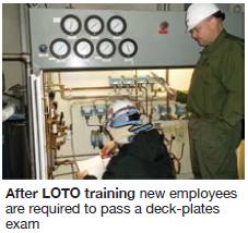
Also, LOTO training and qualification are mandatory for new hires. After completing LOTO training, new employees are required to pass a LOTO practical factor demonstration (photo) administered by the operations supervisor or lead operator within three to six months of hire that includes the following:
- Oral interview—including such topics as how to perform a start attempt, perform a second check, file a report following tag/lock hanging.
- Successful completion of a LOTO hanging on selected equipment—including a verbal report and proper start attempt on the LOTO equipment;
- Successful second check of a previously hung LOTO that includes intentionally introduced errors (valve out of position, lock/tag hung on wrong isolation point, etc) derived from previous Whitewater LOTO lessons learned.
 Employees often fail their first attempt at the practical factor, in which case they must try again at a later date. The objective is to eliminate mistakes by shaping focus and behavior regarding lockout/tagout through training and qualification.
Results. Since implementing the new program in late 2014, plant has had no lockout/tagout violations. Plus, there has been a reduction in leading indicators—fewer verbal reports, fewer errors in LOTO form paperwork, etc—associated with lockout/tagout.
Project participants:
Randy Culler, lead operator
Dan Tesch, maintenance supervisor
Mark Barrett, operations supervisor
LSP-Whitewater LP
Owned by Tyr Energy
Operated by NAES Corp
275-MW, dual-fuel, 1 × 1 combined-cycle cogeneration facility located in Whitewater, Wisc.
Plant manager: Roy Killgore
