


Clyde V Maughan, Maughan Generator Consultants
Carbon-brush collectors have successfully transferred current from excitation power sources to the rotating fields of synchronous generators for over a century. The basic principles of current transfer have remained the same over that time, although numerous improvements have been made in brush and collector-ring materials, brush-holder designs, and ventilation arrangements.
Still, carbon-brush collectors require ongoing attention from O&M personnel. While this work is of a relatively minor nature, the collector operates at 100 to 700 Vdc in a very noisy and windy environment. Thus there is an understandable reluctance on the part of plant staff to perform the necessary online service of the brushes and collector.
The result: Collectors are sometimes overlooked, and failures occur. Such failures can be severe and the resulting forced outage may be long and costly.
Rotating rectifiers have gained market share on carbon-brush collectors since the late 1970s because of the latter’s need for ongoing attention, and the occasional failure. Rotating rectifiers generally have given good service, particularly on small generators. However, rotating rectifiers have inherent limitations and weaknesses, and carbon-brush collectors still are preferred for large machines. Remember, too, that carbon-brush collectors are installed on tens of thousands of generators in service.
Carbon-brush collectors will give high reliability, provided the generator OEM’s recommendations are followed. Keep in mind that the O&M procedures summarized in this article apply to carbon-brush collectors in general; consult the OEM for information specific to your equipment.
Basic principles of collector operation
Generator performance is monitored by many devices. But even with state-of-the-art instrumentation, several important generator deterioration mechanisms are not monitored at all—including those associated with the collector. This means that collector condition must be determined by looking directly at the collectors and brushes themselves—a requirement often cited as the primary reason collectors sometimes are neglected and subsequently fail in service.
Collectors require continual minor attention, primarily because of brush wear. Although providing this attention may seem like an inconvenient chore, it is an extremely important function of the O&M staff. Fortunately, collectors almost never fail without ample warning, so regular observation allows plant personnel to spot and correct potential trouble long before a failure can occur.
Simply put, reliable collector performance requires the following actions:
- Making daily direct observations.
- Recognizing the warning signals of impending failure.
- Taking timely corrective maintenance action.
Keep in mind that dependable brush-to-collector current transfer relies on the following three conditions, which must he satisfied simultaneously:
1. Good collector surface film. Correct balance is needed between the film-forming and the polishing actions of the brush on the collector ring. Balance depends on the brush material (usually natural graphite with a small amount of abrasive material and suitable binder), and on the ring material (typically hardened steel on large generators). Contaminants in the cooling air can adversely influence this balance, as can low humidity, since water molecules are a necessary ingredient of a good film.
2. Proper brush contact pressure. Satisfactory transfer of current between the brush and the ring demands that contact pressure be maintained within limits established by the manufacturer. This means that the brushes must not hang-up in the holder and that the spring pressure must be correct.
Early machines were supplied with a helical-coil-spring brush holder, which required periodic manual readjustment of the spring force to compensate for brush wear. Brush holders with a constant-pressure spring are now common, and they have virtually eliminated problems caused by improper contact pressure.
3. Continuous brush-to-ring contact. When a collector ring and its brushes are not in continuous contact, arcing results. Once arcing becomes visible, operating performance deteriorates rapidly. Thus arcing should be recognized immediately as a warning of impending serious trouble.
Loss of continuous contact is caused by excessive brush vibration, which can be cured only by reconditioning the collector-ring surface. This assumes that the shaft excursion caused by unbalance is acceptable.
Causes of collector outages
Collector outages usually are caused by (1) a planned outage to resurface the collector, or (2) a forced outage caused by collector flashover.
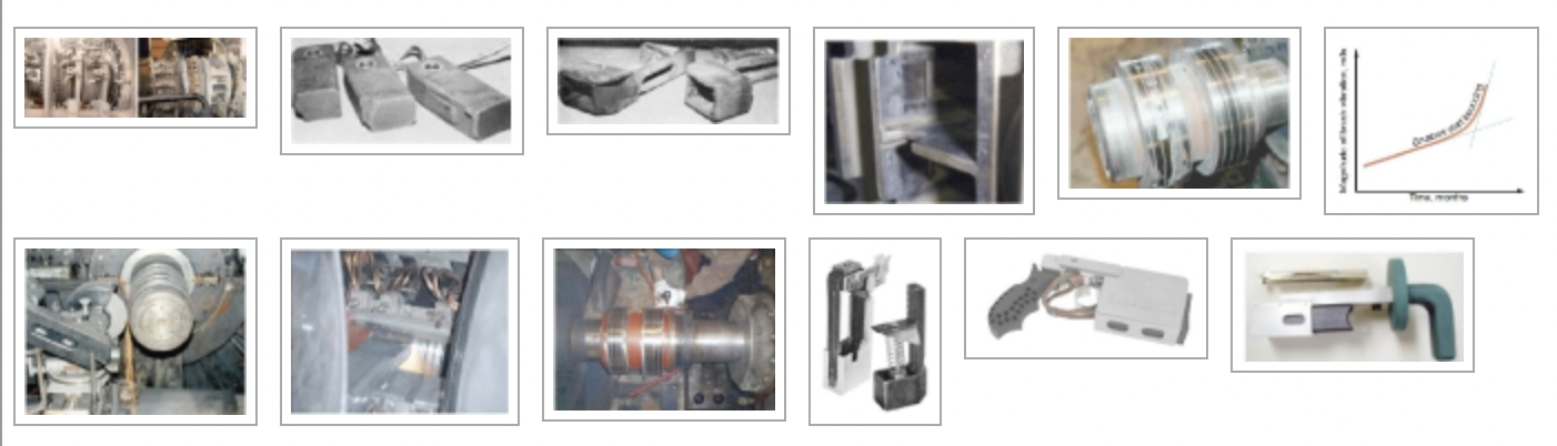
Flashover is a term that describes the opening of the highly inductive generator field circuit at either one or both collector polarities. Typical consequences of flashover are shown in Fig 1. Arcing between the brushes and the associated pair of rings of one polarity is evident in the left-hand photo. The result is burning of the brushes and arc damage to the ring surfaces of the one polarity. The ring of opposite polarity—at left in the photo—remains undamaged.
In the right-hand photo, the flashover involved both polarities and the arc damage was great. The associated arc would present a severe hazard to any operator in the area. Temperatures were sufficiently high to distort the forgings of the fan between the polarities. The appearance suggests that shedding of rotating parts, with associated extreme hazard to personnel, was imminent.
Breakdown of the insulation separating the two polarities, which are at different but low electrical potentials, is a rare occurrence. The open circuit results from a progressive loss of contact between the ring and brushes which causes current transfer by arcing across the gap until the gap becomes too large for the arc to be sustained. This action is similar to very slowly opening a knife switch in an inductive circuit.
To compensate for the energy lost during heavy arcing prior to flashover, the automatic voltage regulator simply calls for higher exciter output to keep the generator terminal voltage constant. This action can be identified indirectly by the presence of erratic and generally higher-than-normal temperature indications on the generator field temperature recorder (because the recorder uses the quotient of excitation voltage to current, both measured on the brush-rigging side of the collector).
Lesson learned: Do not assume that erratic behavior of the generator field-temperature recorder means the instrument is malfunctioning. If the temperature recorder is giving erratic readings, immediately check the collector for arcing.
Identifying problems
As noted earlier, reliable collector performance depends on a good surface film, proper brush-contact pressure, and continuous brush-to-ring contact. What follows are several suggestions on how to identify an impending failure, as well as some guidelines—best practices, if you will—for corrective maintenance to help avoid a turbine/generator forced outage.
Ventilation. High-capacity collectors are cooled by forced convection, typically with ventilating air pumped by shaft-driven fans. Proper ventilation is important for preventing overheating, which can result from (1) blocked passages in intake or exit ducts, (2) plugged ventilation holes in the collector rings themselves, or (3) plugged filters.
The initial effect of overheating usually is increased brush wear, but high wear rates can lead to other, more-serious problems. Temperature of the collector inlet and outlet cooling air is monitored to gage collector ventilation performance. Important: Pay close attention to the OEM recommendations on temperature-rise limits.
Surface-film contamination. Contaminants in the cooling air—such as oil vapor, ammonia, abrasive dust, insects, vapors from silicone rubber, etc—impede the formation of a good, stable film on the collector rings. The film, consisting of layers of metal oxide, graphite, and adsorbed water vapor, lubricates the contact surface. Without this lubrication, brush friction would increase dramatically, causing excessive wear, chatter, and brush breakage (Fig 3).
Film quality is not easily discernible by looking at a collector ring; plus, there often is more than one possible cause of any observable symptom. The search for answers is made more challenging by the simple fact that contaminants and their sources of origin typically are difficult to identify.
Solid contaminants usually can be removed from cooling air by proper filtration, and by sealing intake leaks around pipes and bus work. To avoid the potential for cooling problems caused by reduced air flow as the filters collect particulates, consider specifying an impingement filter. It will pass dirt along with air as the filter approaches its holding capacity, thereby avoiding plugging and consequent overheating.
Regardless of the type of filter installed, focus on your filter’s ability to maintain the level of cleanliness required.
Gaseous contaminants originating in the plant, such as oil vapor from bearings and pipe joints, can and should be eliminated at their sources. However, gaseous contaminants from sources external to the powerplant—such as a nearby chemical plant—generally cannot be eliminated and they require adoption of more rigorous maintenance practices.
When developing a collector-ring program to suit your situation, keep in mind that the residue of common cleaning solvents left on the rings itself is a serious contaminant. Suggestion: After cleaning rings with a solvent, clean the ring surface again with alcohol and carefully wipe it dry.
Another idea: Periodic application of a canvas wiper (one made from canvas not treated with chemicals) can, under some circumstances, prevent excessive buildup of contaminants on the ring surface.
Mixing or misuse of brush grades. The performance of an individual brush on a collector depends heavily on the brush’s properties. Tight quality control is maintained by the brush manufacturer to hold the properties of each brush grade within a very narrow band. Despite such efforts, even brushes of the same grade will not necessarily share current equally—that is, they may exhibit some selectivity.
Mixing of brush grades on the same ring can lead to intolerable selectivity, which may cause a pigtail to burn off and make that brush inactive. The remaining active brushes will overload as a consequence, and a runaway condition may start. This could lead to collector flashover.
The original brush grades recommended by the turbine/generator manufacturer normally should be satisfactory. However, if difficulties are experienced, consult the OEM before finalizing your decision on a new brush grade.
Also, before installing brushes of a new grade, be sure to clean the ring surface down to bare metal, using guidelines provided in the generator manufacturer’s instruction book. This allows the new brush grade to form its own characteristic film. After switching brush grades, discard all brushes of the old grade to avoid subsequent mixing.
Brush contact pressure. Failure to maintain correct spring pressure has been a frequent cause of collector flashover. Proper pressure is required to (1) keep brushes in contact with the ring, and (2) have all brushes carrying a near-equal share of the current. Brush holders using helical-coil springs require periodic spring tension adjustment to compensate for reduction in brush length because of wear; constant-pressure springs do not require such adjustment.
Brush current density. While often overlooked, incorrect brush current density can cause serious operating problems. Examples: Too-high density causes brushes to run hot; too-low density is conducive to high brush and ring wear.
Experience suggests that a current density of around 50 amp/in.2 of brush contact area is a reasonable rule-of-thumb target for typical brush grades. At 60 to 70 amp, most brush grades will operate too hot; at 30 amp, a poor film is likely to exist.
If brushes are wearing rapidly, or if they are running hot, operation may be improved by removing or adding brushes, respectively. However, before changing the number of brushes from the original design, contact the OEM for specific recommendations.
Brush hang-up and chatter. Brushes can hang up in their holders for various reasons, including the following:
- A buildup of contaminants and/or carbon, restricting free motion of the brush (Fig 4).
- Brush worn too short, allowing the pigtail to rub against the box.
- Size incompatibility between brush holders and brushes.
- Brush chatter.
The most common cause of brush hang-up is chatter, a term that describes tangential brush vibration. It is attributed to high or non-uniform friction around the ring periphery—which, in turn, usually is caused by ring contamination.
If the brush does not ride smoothly on the ring, and chatter results, the top edge of the holder can wear a ridge in the side of the brush. The brush may then sit on the ridge and not respond to spring pressure. Thus, the brush becomes unloaded electrically. If enough brushes hang up, arcing will start, and may eventually result in a flashover.
Practical idea: Detect hung-up brushes by visual observation, or by feel with an insulated stick. If vibration feels unusually low on an individual brush, it may not be riding on the ring surface.
Short brushes are another major cause of flashovers. When brushes reach the end of their useful wear length, they must he replaced. Consult the OEM’s instruction book for recommendations.
Continuous brush-to-ring contact. Excessive collector vibration can cause brush bounce, arcing, and ultimately, a flashover. Thus, it is important to monitor the magnitude of brush vibrations, and the dominant frequencies of several specific brushes. Assuming unchanged generator balance, expect brush vibration to increase slowly over a long period of time, because of collector-ring wear. Generally, a series of peaks and valleys form around the periphery of the ring (Fig 5); also, ring contour may vary from brush track to brush track.
If vibration increases to high levels, there comes a point when the brushes are no longer able to maintain contact with the ring around its entire periphery and they start bouncing and arcing. Under such conditions, arc erosion of the ring surface quickly deepens existing valleys. From this point, vibration increases much more rapidly with time (Fig 6), causing brush chipping and breaking, and ultimately, a flashover if it is not corrected.
There is no characteristic level of brush vibration that signals the onset of brush bounce, because the outward radial force on the brush depends on brush mass and acceleration, not displacement. Fairly high radial displacements—that is, those attributed to shaft unbalance—can be tolerated on 50- and 60-Hz equipment.
But if peaks and valleys develop in the ring periphery, higher vibration frequencies will result and there will be higher forces on the brush. Since acceleration is proportional to the square of the frequency, these forces may become quite high.
The electric power industry generally accepts brush-vibration magnitudes of less than 6 mils for collectors on 3000- and 3600-rpm generators. Severe problems usually begin to occur soon after vibration-induced displacements increase beyond about 10 to 15 mils.
Best practice: Monitor the vibration of selected brushes weekly and plot vibration magnitude against time. If vibration begins to increase rapidly with time, investigate the condition immediately and take corrective action.
Ring resurfacing. Corrective action on collectors can include ring resurfacing by grinding or stoning. In extreme cases, machining is required before grinding. There are two acceptable methods for grinding and truing rings:
- On turning gear, with a rotating grinding wheel (Fig 7). The objective is to get the collector ring round, and if the shaft is balanced properly, that is how the ring will appear to the brushes at speed.
- At rated speed, with a rigid stone (Fig 8). The objective is to compensate for shaft vibration by making the ring appear round at speed. In other words, you “grind out” the vibration. However, any later changes in rotor balance also will change the effective ring contour.
Both methods, when properly done, give the brushes a smooth, continuous, polished surface on which to ride.
Consider periodic collector-ring resurfacing routine maintenance. Collector rings have sufficient stock to last the lifetime of the generator. However, if you must resurface a ring more frequently than once every two or three years, it’s a good idea to identify the reasons for the ring-surface deterioration and take corrective action. The penalty for not being proactive may be excessive maintenance and eventual collector replacement. If ring wear reaches a point where the spiral grooving must be re-established, this can be done with the field in place (Fig 9). Eventually, however, the ring must be replaced if mechanical stress limits are approached.
Retrofitting brush holders
A review of industry experience indicates that a primary reason for collector problems—flashovers in particular—is the failure to perform the relatively minor routine inspection and maintenance tasks required for reliable operation. There is legitimate concern with hazards to personnel and equipment because of the need to adjust and replace brushes while the generator is operating.
Though field voltages are relatively low and the field is intended to operate ungrounded, a possibility exists that a ground may have developed. Also, there still exists the voltage between rings. Furthermore, even if excitation voltage has been removed from the field, the ground detection voltage still may be applied—about 125 V.
However, reliability of the brush/collection system has been highest, and generally has met expectations, on generators equipped with brush holders (1) having constant-pressure springs and (2) being of the removable-cartridge (magazine) type.
Such brush holders have been available for 45 years, particularly on very large generators. The removable holders allow close inspection and replacement of brushes with minimal personnel exposure to hazardous conditions. The constant-pressure springs eliminate the need for constant adjustments to the holders to compensate for brush wear, thus further reducing the need for contact with the excitation voltage.
Retrofit of existing collectors with removable brush holders is possible. One such retrofit has been available for 35 years (Fig 10). This early General Electric design was a little awkward to handle, not structurally solid, and used a helical spring. Other replacement cartridge holders have recently become available, including these:
- The Cutsforth Inc holder (Fig 11) requires change-out of the buss rings to implement. Once the new brush holders are assembled to the new busses, brush replacement is easily and quickly accomplished, although the pig-tail location requires use of insulating gloves. This design incorporates a new spring with each proprietary replacement brush.
- The Fulmer Co holder (Fig 12), by contrast, is a direct drop-in replacement to the existing holders, and does not requiring drilling of holes or change-out of the buss rings. Thus the conversion can be done during a short shutdown (one shift for a 48-brush collector). Brush replacement with this holder can be performed without insulating gloves.
Retrofit with well-designed, removable brush holders greatly simplifies brush replacement. Exposure to collector-ring voltages and high windage noise are significantly reduced. Attenuation of these hazards should result in much less reluctance by plant personnel to servicing a collector on an operating generator. In turn, this should appreciably reduce the likelihood of collector problems, including flashover, on the generator. CCJ
Clyde V Maughan is president of Maughan Generator Consultants, Schenectady, NY. He has 60 years of experience in the design, manufacture, inspection, failure root-cause diagnostics, and repair of generators rated up to 1400 MW from the leading suppliers in the US, Europe, and Japan. Maughan has been in private practice for the last 24 years. He spent the first 36 years of his professional career with General Electric Co.
This work is an updated and expanded revision of an article the author and his GE colleagues (H O Ohmstedt, J S Bishop, and W J McMillian) prepared for publication in Power magazine nearly 35 years ago. The editor who commissioned that piece currently is editor of the COMBINED CYCLE Journal.