Rotor disassembly basics, repair case histories
Rotors have become a top discussion topic at user-group meetings as gas turbines rapidly add hours and starts in these days of must-take renewables and low-price gas, stoking end-of-life concerns for critical rotating parts. Relatively few plant personnel have first-hand experience in rotor overhauls. Most have not had the opportunity to participate in unstacking, inspection, repair, restacking, and balancing activities. It is important to have perspective on these matters before you get involved with rotor work in a meaningful way.
Sulzer Turbo Services’ Engineering Advisor Fernando Romero offered owner/operators attending the 2012 meeting of the 501F Users Group last February an instructive look at the dismantling of an 501FD2 rotor, inspection of its component parts, appropriate rotor repair methods, and reassembly. He told an audience of nearly 200 users at the Saddlebrook Resort in Tampa that his company had done work on a dozen such rotors, dismantled six, and found failed components on two of the six.
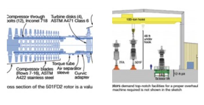
The first part of Romero’s presentation was a valuable primer on the general design and configuration of the FD2 rotor, the dominant 501F-series model in service today. Important to note is that this machine differs dramatically from the 501FD4, Siemens Energy Inc’s latest F-class production engine. The FD4 has three fewer compressor stages than the FD2 and variable guide vanes on three stages rather than one as on the FD2.
A cross section of the 501FD2 rotor is presented in Fig 1. As the Fig 2 shows, it is a few feet longer than the competing 7FA engine from GE Energy. The FD2 is 32 ft long overall, divided among the compressor (18 ft), torque tube connecting compressor and turbine (4 ft), and the turbine (10 ft). Total weight of the bladed rotor is 54 tons. The machine is equipped with 1193 compressor blades and 334 turbine blades.

Unstacking begins after the rotor is moved to the pit by the bridge crane. First step is to relax the 10 turbine through bolts. This is done by stretching the bolts to (1) release the contact forces between adjacent disks and (2) to remove the nuts (Fig 3).
However, before removing the nuts, technicians “mike” the bolts and record stretch data to determine if there’s a problem caused by uneven tension or a cracked bolt. The R4, R3, R2, R1 wheels are then lifted off one at a time (Fig 4). Note that the Siemens turbine wheels do not have rabbet fits like the GE frames.
The component you see after removing the first-stage turbine wheel is the curvic clutch adapter. It sits on top of the torque tube. The air-separator sleeve slides over both and bolts to the flange on the torque tube. After the air-separator sleeve is removed (Fig 5), the compressor through bolts are relaxed, the torque tube is picked by the crane, and compressor disks are unstacked.
For compressor stages 5 through 16, dry ice is used to shrink the suction (male) sides of the wheels (Fig 6), which mesh with the discharge (female) sides of adjacent wheels, to free up the interference fit. This allows removal of each wheel in turn without galling rabbet surfaces. Stage 4 differs in that it has female fit-ups on both sides of the wheel and heat may be needed to remove it. The first three compressor stages are integral with the stub shaft.

Repair case histories
The first case history Romero discussed was a rotor that had been removed from operation because of high vibration resulting from a turbine blade failure. The aft end of the third compressor stage had high run-out and a 360-deg, 1-in.-deep crack was found at the third-stage pilot location (Figs 7, 8). The pilot, designed with an internal thread to facilitate lifting, was machined off to conduct a metallurgical analysis of the crack (Fig 9).
There were initiation points and beach marks all around the circumference. Fracture surfaces showed evidence of heating, rubbing, and beach marks indicative of fatigue (Fig 10). Corrosion pits were easy to see on the OD of the rabbet fit under an optical microscope. A scanning electron microscope revealed corrosion pits at the crack initiation sites.

The rotor showed no signs of intrinsic material defects that could have contributed to this failure, Romero said. However, corrosion pitting was linked to the dozens of initiation sites found at the OD of the part. An insert was designed to take the place of the pilot, which is only used for assembling the machine (Fig 11). The design was qualified by using finite element analysis (Fig 12).
Second case history. The rotor, taken out of service because of a lube-oil-system failure, did not exhibit abnormal vibration or run-outs. However, both the compressor and turbine shaft ends suffered heavy rubs in the oil-seal area. Plus, the pilot had failed completely and was hanging from the fourth-stage disc. Journal surfaces were repaired by submerged arc welding (Fig 13), then the shaft was stress-relieved and finish-machined (Fig 14).

Romero pointed out that the pilot “wasn’t going anywhere” and had the rotor not been unstacked to facilitate the rub repair no one would have been the wiser. However, he said, you don’t want to leave an untreated scar even if it’s not an imminent threat. The same solution used in the first case history was applied in the second. CCJ


