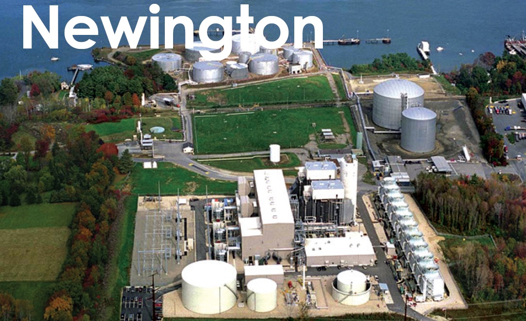
Essential Power Newington
Owned by Essential Power Investments
Operated by Cogentrix Energy Power Management
565-MW, dual-fuel 2 × 1 combined cycle located in Newington, NH. Plant operated baseload from COD in 2002 until it began cycling in 2008
Plant manager: Tom Fallon
Electronic safety orientation program for contractors
Challenge. Essential Power Newington annually processes hundreds of contractors through its site-specific safety orientation program, consisting of an instructional safety-related video and certificate of completion. The rate of certifications increases significantly during outage periods.
The challenge of completing site safety and compliance training efficiently and effectively without impact to outage work schedules can be demanding. Beginning in early 2020, and continuing through 2021, Covid-19 concerns limited personal interaction and congregation in an effort to minimize risk of transmission. With contractors arriving from all areas of the country, the site explored digital and remote avenues which had not been invested in previously.
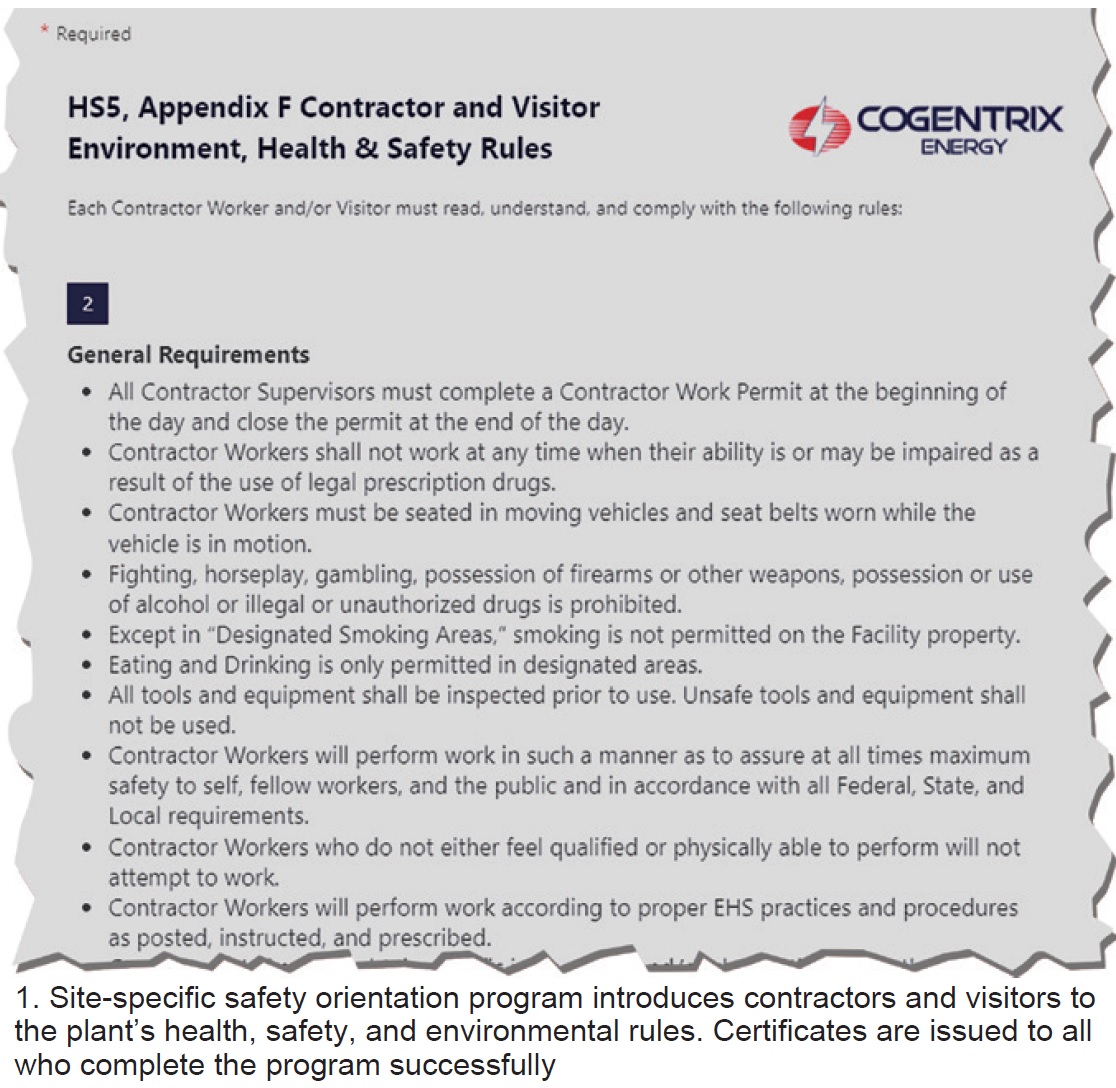
Solution. Staff explored various electronic resources to deliver its safety orientation video, facility EH&S rules (Fig 1), and NERC CIP compliance protocols to personnel arriving onsite. Critical quality features included the following: (1) ease of use for the end user and administrator, (2) ability to edit content as needed going forward, (3) compatibility with mobile phone use, and (4) ability to electronically verify completion.
Microsoft Office 365’s Forms program was the solution selected. It has the ability to e-mail contractors/vendors a message with an optional QR code and/or forms.office.com hyperlink.
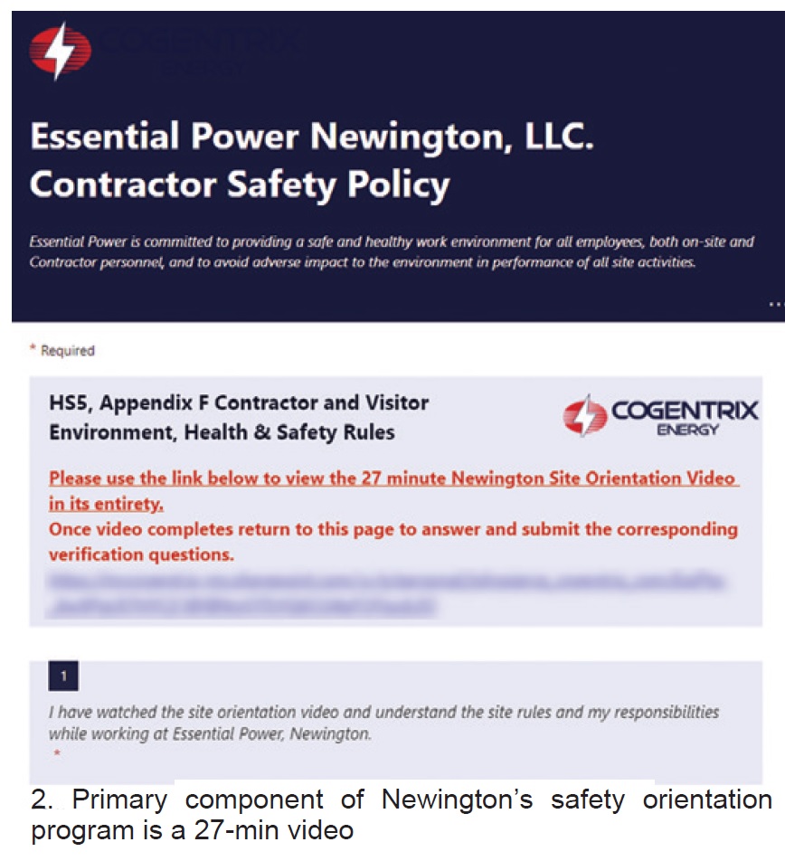
Use of a mobile device and QR code allows quick navigation and orientation, and completion of required tasks. A hyperlink also is provided for PC use. Once the user receives the e-mail and accesses the form using either the QR code or link, he or she is able to review a customizable and site-specific embedded SharePoint link to the site’s 7-min orientation video (Fig 2).
There also are several easily navigable electronic forms to review and verify completion.
Once the video has been watched and the form completed, the user initials the electronic form and submits it to the site’s EH&S manager. From there, data are compiled in a user-friendly electronic database for staff to review and to track the completion status of contractors. Electronic timing of form completion identifies potential attempts at subversion of the orientation process.
Results. The Office 365 Forms program has been tested by several employees and found effective and easy to use. Having the ability to watch the video and review and submit the electronic form from a mobile device provides contractors a user-friendly method for completing site orientation from outside the plant prior to arriving for the Newington outage.
Plus, electronic submission frees up significant paper resources and filing requirements.
Also, headcounts onsite in contractor orientation workspaces are reduced to those infrequent occurrences where electronic submission was not feasible ahead of time. When prequalified contractor personnel arrive onsite, they immediately report to the specified Point of Contact (POC) and receive their orientation-completion hardhat stickers.
The POC is able to quickly review orientation completion status in the electronic repository and directly answer any questions relevant to the training in the context of the contractor’s work scope.
In sum, investment in electronically facilitated site orientation saves resources and time and the efficiency of contractor safety- and compliance-training certification.
Project participant:
John Pierce
Upgrade to boiler-water sample panel helps ensure proper chemistry
Challenge. EPC engineers integrated a firetube boiler into the design Essential Power Newington for use during cold-plant startups to provide steam for turbine seals and HRSG sparging. The auxiliary steam system includes a deaerator supplied with cold demineralized-water makeup. Aux boiler use for HRSG sparging has increased as the plant moved from its original baseload operating profile to more of a seasonal peaking operation.
Sparging can be necessary for days at a time, or longer, depending on market dynamics and ambient temperature. Treatment chemicals are added via small electronic metering pumps. Chemical-pump stroke rates are adjusted manually based on grab-sample analysis in the water lab by an auxiliary plant operator. The original construction did not include any continuous analyzers to ensure proper control of boiler-water chemistry.
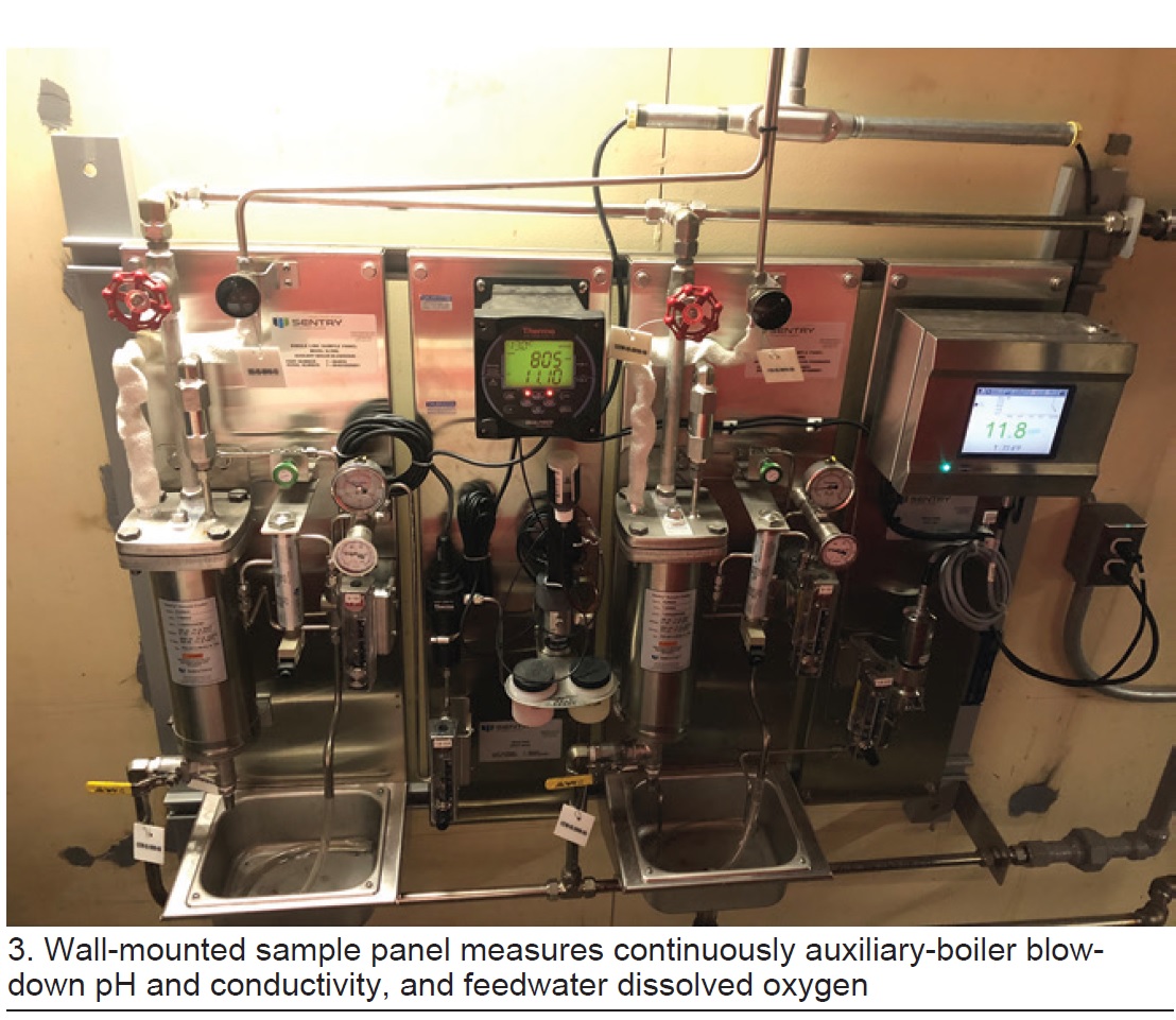
Solution. Site personnel reviewed water-chemistry key parameters for the low-pressure firetube boiler, selecting these three characteristics for continuous measurement: blowdown pH and conductivity, and feedwater dissolved oxygen. Staff then worked with a vendor to design a sample panel to measure the three variables using sampling equipment currently used onsite in the HRSG sampling system (Fig 3).
The final challenge for design of the sample panel was to find a location in the aux-boiler building where the panel would be close to the sample sources while also allowing O&M personnel proper access to other equipment. This involved minimizing the wall panel’s depth to maximize aisle space.
Results. Personnel completed installation of the sample panel during a recent plant outage. Analyzer outputs were wired to the DCS, where screen graphics were added and alarm triggers set. The analyzer outputs also were added to the PI historian for long-term trending and alerts.
While several additional continuous analyzers would be necessary to automatically control boiler chemistry, these three continuously measured characteristics help ensure proper chemistry maintenance between grab-sample analyses.
Project participants:
Kyle Malenfant, I&E technician
Michael Dill, I&E technician
Eric Pigman
Automating chemical injection key to tighter control of cooling-tower operation
Challenge. Because Newington was designed to operate baseload, it did not have an automatic scale-inhibitor injection system for the 1.5-million-gal saltwater cooling tower, which operates at 2.0 cycles of concentration and has a 150,000-gpm recirculation rate. A single salinity meter was installed on the circulating-water-pump discharge but there was no means for measuring makeup-water salinity continuously to accurately monitor for tower cycles.
The chemical treatment program for scale and dispersant control is an HEDP/polymer combination, which is injected into the tower basin. River-water makeup quality, 2.0 cycles of concentration, high surface temperatures in the condenser, and desired operating pH range were used to arrive at the optimal concentrations of treatment chemicals. A buffer is included to allow for routine fluctuations in makeup-water quality or upsets.
Given water-sample testing interferences with tower salinity, injection feed rates were based on blowdown flow rates, adjusted manually. This led to many occurrences of over- and under-injection because blowdown rates can fluctuate daily and seasonally.
Solution. Two new chemical-injection metering pumps were installed with microprocessor controls. The scale-inhibitor pump injection controls now run in automatic via a 4-20-amp control signal based on tower blowdown flow rate. In addition, a salinity meter was installed at the river makeup source to accurately monitor for tower cycles for tighter control.
These changes are conducive to a better tower chemistry program, one with both consistent scale protection and chemical control ranges. The makeup-water salinity instrument ensures consistent as-designed tower cycles, which, in effect, increases the concentration in the tower, and by automating the scale-inhibitor pumps, reduces chemical consumption. In sum, these changes reduce chemical costs and maintain a tighter tower-chemistry control program.
Results. With additional training on blowdown control rates and chemical injection operations, the control for combatting scale in the surface condenser is much tighter. Having accurate tower cycles, because of the added makeup salinity meter, allows staff to better regulate tower blowdown and injection feed rates to accurately manage the system during all operational profiles—while still offering opportunities for reductions in chemical consumption.
The scale-inhibitor automation improvement allows for less manual intervention when tower blowdown rates are fluctuating frequently based on plant operating profiles.
Project participants:
Joshua Leighton, Eric Pigman, and Scott Courtois
 Warning lights for overhead doors make plant safer for staff, visitors
Challenge. Large overhead roll-up doors are a concern in industrial workplaces—a recognized hazard that could cause serious physical injury or equipment damage if not acknowledged and controlled. Reasons include these: They are heavy, may fall closed while traveling if the head works fails, and may not be equipped to auto-reverse when they come in contact with an object or person.
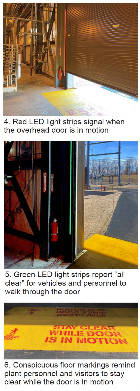
Solution. Staff analyzed options for improving the safety and communications protocols for traversing through the plant’s large 20 × 20-ft turbine-hall overhead doors (Fig 4), commonly used by a large number of people. Visual indicators were deployed to provide additional warning and to remind personnel and visitors about overhead-door safety and site expectations.
Industrial LED light strips were a practical solution. The power and controls for them are incorporated easily into the operation of the door opener while providing warning lights by flashing RED when the door is in motion. Once the door reaches its fully open limit switch, the light strips turn solid GREEN (Fig 5). When the door moves closed, the LED strips again flash RED until the door fully closes against the pressure limit switch; the lights shut off after 30 seconds. The warning-light system is installed on both sides of the door frame, and both inside and outside.
In addition, large floor markings were developed to remind walking personnel to use the adjacent walk-through door for exiting and entering the turbine hall rather than an overhead door.
In conjunction with installation of the light strips on the door frame and conspicuous floor markings (Fig 6), the site instituted a standing directive that the doors not be driven or walked through while in motion. They can be traversed only when in the fully open position and the lights are solid GREEN.
Results. Use of visual stimuli to let staff and contractor personnel know a door is in motion, and communicating that you must not drive/walk through an overhead door in motion, has helped to prevent equipment damage and other safety events. While nothing is fail-safe, the addition of warning lights and floor markings remind about site protocols and the need to wait for the fully open status before moving through.
Project participants:
Mike Dill, I&E technician
Kyle Malenfant, I&E technician