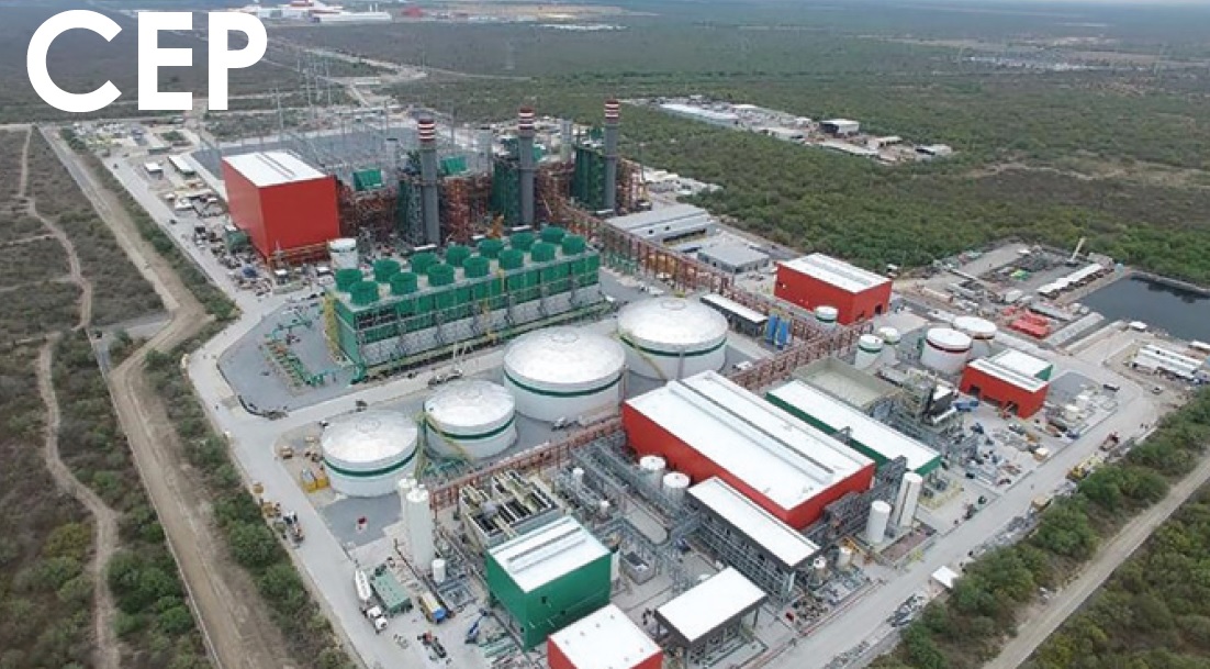
Central Eléctrica Pesquería (CEP)
Owned and operated by Techgen
900-MW, 7FA.05-powered 3 × 1 combined cycle located in Pesquería, Nuevo León, Méxicó
Plant manager: Mario Alberto Ontiveros de la Torre
‘Improved’ brush holder offers safety benefits
Background. CEP’s four generators are equipped with the OEM’s EX2100e excitation system to control ac voltage at the generator terminals and/or reactive volt-amperes (VAr). Plant’s excitation system has a collector on the free side of the generator, where carbon brushes transfer the excitation current to the rotating slip rings and produce an electromagnetic field in the generator.
Incident. During normal monthly preventive maintenance, the following occurred when changing a brush on the negative pole: Technician inserted the brush holder, using its insulated handle (Fig 1), unaware that the carbon brush had slid out and been pushed to the middle space between the collector rings. The resulting electric arc damaged the rings and generator rotor.
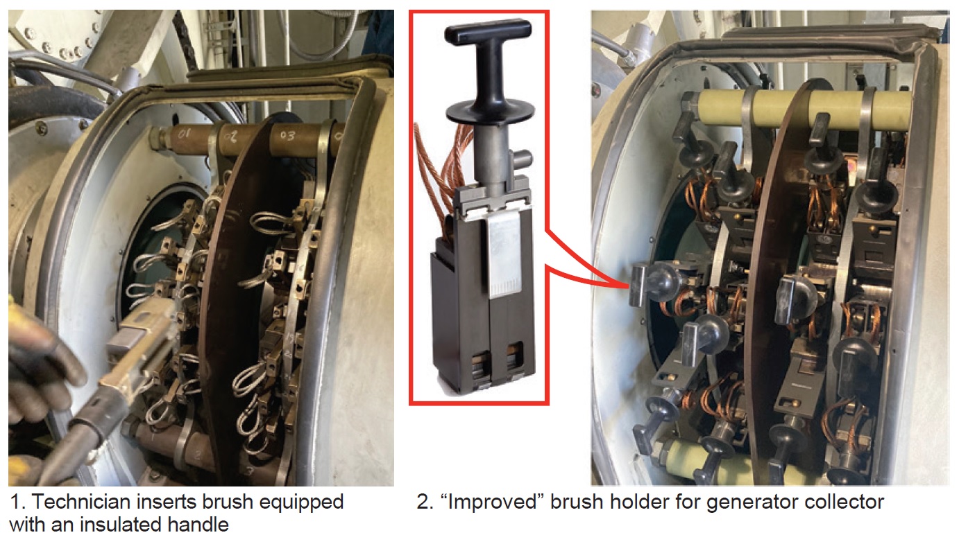
Solution. After the event, the maintenance and technical control team conducted a root cause analysis (RCA) and investigated collector-brush-system replacement options. GE’s “improved” brush holder (Fig 2) was selected for the following reasons: (1) Reduced the possibility of contact with live brushes, a significant safety benefit; (2) Provided higher reliability by eliminating incomplete insertions; and (3) Assured higher availability by reducing the risk of collector discharges.
Plus, brush wear can be seen easily through the inspection window, or by inspecting the wear indicator on the brush pigtail.
Results:
- Separation from energized components makes for a safer system, especially when changing out brushes with the turbine/generator in operation.
- Reduced risk of brush hang-ups.
- Tool-less maintenance given the permanently attached handle, which also reduces the time required for brush change-out.
- Reduced risk of collector flashovers.
- Increased brush size/life.
- Lightweight aluminum construction with a durable and anodized surface coating.
- Less susceptibility to brush-current selectivity (uneven current distribution between brushes).
- Direct replacement of single-wide holders without modification to the brush rigging.
Project participants:
Arturo González, technical control chief
Odon Acosta, maintenance chief
Arturo Macías, electrical coordinator
Copper braids outperform carbon brushes for shaft grounding
Challenge. Eliminate an unsafe condition present in the grounding-brush systems for CEP’s gas turbine/generators and implement an operating practice to enhance personnel safety and reduce the risk of equipment damage during routine maintenance.
The original grounding-brush system has a spring-type lock (Fig 3 left) that must be pulled and removed to release the brush for replacement or to perform maintenance, which sometimes must be done with the generator in operation (Fig 3 right).
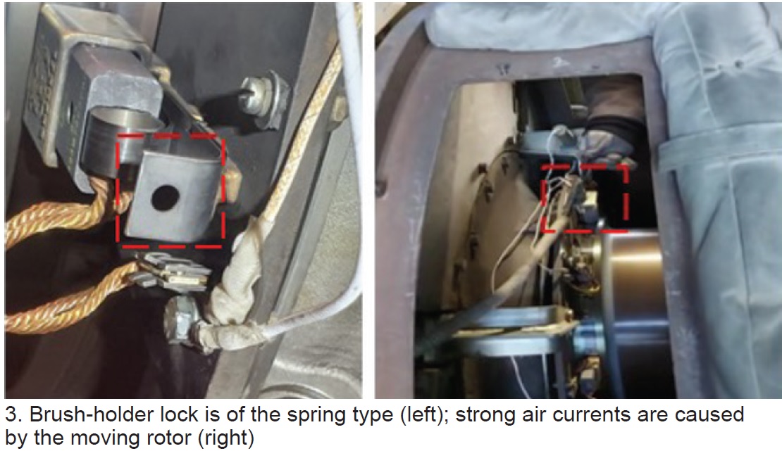
These factors are conducive to an unsafe condition because of the close distance between the operator and the working generator—a noisy environment with strong air currents.
Solution. After an exhaustive analysis by technical staff, an alternative grounding system was identified—one similar to that used in the steam turbine/generator. It uses copper braids that are extracted easily by pulling the fixing lever (Fig 4 left) and removing the braid to the side (Fig 4 right).
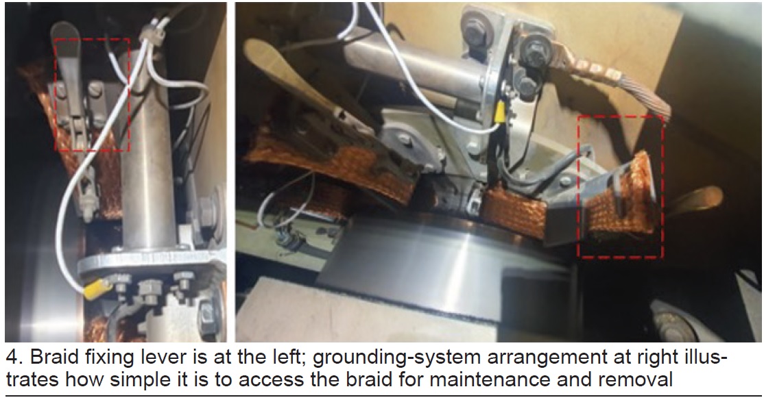
The new grounding system reduces the time required for maintenance: It is of simpler design than its predecessor and maintenance consists only of cleaning with dielectric solvent and verifying that the braid is not too worn (or replacing it if it is).
For insertion, the braid is placed on one side and pressed with the locking lever and it is ready for operation.
Results. The increased accessibility afforded by the new grounding system allows handling the components at a safer distance than previously—further away from the rotating machinery. Plus, the maintenance interval has been extended from one month to two, making the grounding system safer and easier to maintain.
Project participants:
Odon Acosta, maintenance chief
Arturo Macías, electrical coordinator
Plus, Isaí Real, Jorge González, and Jorge Rosalio
Replacement valve actuators provide ergonomic benefits, speed maintenance
Background. CEP has a ZLD (zero liquid discharge) gray-water treatment plant incorporating softening, ultrafiltration, reverse osmosis, and electrodeionization.
Throughput extends to nearly 6200 gpm.
Challenge 1. Reduce or eliminate failures of actuators for valves serving CEP’s five ultrafiltration modules. The original actuators were of a very robust design, each weighing about 200 lb. Thus, their removal for maintenance required cranes and the intervention of specialist personnel from different areas of the plant’s O&M team (Fig 5).
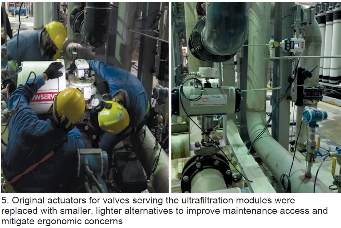
Regular actuator maintenance, typically required every six months because of wear and tear experienced by positioners, instruments, and other components primarily attributed to high vibrations, took about 16 hours. Actuator location complicated maintenance because of ergonomic concerns.
Solution 1 involved replacement of the original actuators with smaller, lighter ones (about 50 lb), thereby improving maintenance access to mitigate ergonomic concerns. Remote positioners were another improvement. Maintenance on the new actuators can be performed in-situ, eliminating the need for cranes and specialist personnel.
Results 1:
- Improved system availability.
- Time required for maintenance cut in half.
- Increased efficiency of maintenance personnel.
- Reduced costs of maintenance and spare parts.
- Less noise.
- Fewer module ruptures attributed to vibration.
- Ergonomic benefits included fewer accidents and fewer injuries to maintenance personnel.
Challenge 2. Increase the availability of the ZLD, which requires a heat exchanger to increase water temperature before it enters the crystallizer. This heat exchanger must be cleaned of scale deposits every two weeks using EDTA and nitric acid to maintain the level of performance required. Cleaning takes from 18 to 24 hours.
Solution 2. A second heat exchanger, independent of the original with all instrumentation required, was installed for use during cleaning turns and as a backup for the original.
Results 2. ZLD system availability and efficiency are assured.
Challenge 3. Eliminate or reduce recurring problems in the sludge-dewatering portion of the gray-water treatment plant. The two dewatered-product transfer pumps in the line to the cold-lime softening system suffered continual impeller damage and mechanical-seal wear, which caused pipes to plug and contributed to excessive maintenance.
Solution 3. The original multistage centrifugal pumps were replaced by single-stage units equipped with mechanical seals lubricated by service water to flush the seal cavity continuously, mitigating wear.
Results 3.
- Improved system reliability and availability.
- Eliminated corrective maintenance; only preventive maintenance is required today.
- Reduced the cost of maintenance and spare parts.
- No lubrication problems were associated with the seal flush system.
- Reduced the cost of system cleaning.
Project participants:
Odon Acosta, maintenance chief
Plus, Moises Arroyo, Daniel Mendoza, Rolando Goytortua, Alma Rivera, Jonathan Herrera, Marco Lopez, Alejandro Domínguez, Juan Carlos Facio, and Luis Melgarejo