


By Steven C Stultz, Consulting Editor
TesTex Inc specializes in electromagnetic non-destructive testing and has developed innovative methods and equipment for combined-cycle HRSG healthcare. Founded in 1987, the company, both multi-industry and global, maintains a focus on heat-recovery steam generators in the challenging combined-cycle world. Its primary mission is fast, accurate, and cost-effective NDT services using pioneering state-of-the-art equipment and expertise.
CCJ connected with TesTex at the HRSG Forum with Bob Anderson. Showcased at the 2018 meeting were proprietary Remote Field Electromagnetic Technique (RFET) equipment for detecting internal tube pitting and wall loss, and a proprietary Low Frequency Electromagnetic Technique (LFET) system to examine finned tubes from the gas side.
The goal of both is to locate and identify pitting, wall loss, caustic and phosphate gouging, corrosion attack including FAC, cracking, erosion, and manufacturing defects. Also on display was the Balanced Field Electromagnetic Technique (BFET), and a curious new contraption called “The Claw.”
TesTex personnel collaborate with both EPRI and ASME to keep a sharp and expanding focus on HRSG challenges and common areas of concern. They take pride in the company’s unique equipment and innovative application skills.
Variety and invention
This editor began professional life in the offshore oil and gas industry, intrigued by what that industry was doing deep in the Gulf of Mexico, and elsewhere. It seems TesTex has some similar roots, using robotic multi-channel sensor arrays (LFET) and automated ultrasonic technology from its Houston office on the massive rigs and platforms with extensive arrays of heat exchangers and piping. Industries do learn from each other.
So when an Alaska pipeline had a containment incident resulting from internal pitting corrosion (a potential shock to the environmentally sensitive North Slope) the US Dept of Transportation put out an urgent call for creative fast-screening NDT. They needed a quick alternative to their primarily manual UT techniques.
TesTex LFET, along with company technicians and NDT engineers, became a critical part of this large-scale, critical and urgent remote-area inspection.
Closer to home, and to the power industry, TesTex developed and applied an ultra-high-speed eddy-current inspection system to a large condenser system, to keep it operating until the next scheduled outage. The condenser contained 18,000 tubes, 40 ft long, and the inspection was wrapped up within five days. Damaged tubes could then be plugged, enabling the owner/operator to get back online.
Balanced field for HRSGs
The TesTex BFET also has an interesting history, plus a recent development labeled “mini- claw.”
“The technology was developed to enhance the signal responses produced from small defects, such as cracks, and specifically for tube-to-header weld issues in HRSGs,” says Shawn Gowatski, manager of the company’s Solution Providers Group. He tells us how it works: Briefly, electromagnetic coils are wound and placed in a balanced state, with the coils in both the x and y geometries at zero potential to each other. “With the excitation coil in the x geometry and the sensor coil in the y, a different signal is produced over defected areas,” says Gowatski.
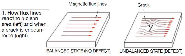
“The alternating current produced by the excitation coil is uniform and undisturbed if no defects are present. If there are defects, the current is interrupted and the current is forced to travel around them in distorted fashion. This produces an indication that signals a defect, and this can be both detected and then quantified by applying proper calibration standards” (Fig 1).
BFET can test different types of metal by adjusting the test frequencies, which range from 100 to 30,000 Hz, and can test at speeds up to 1 ft/sec.
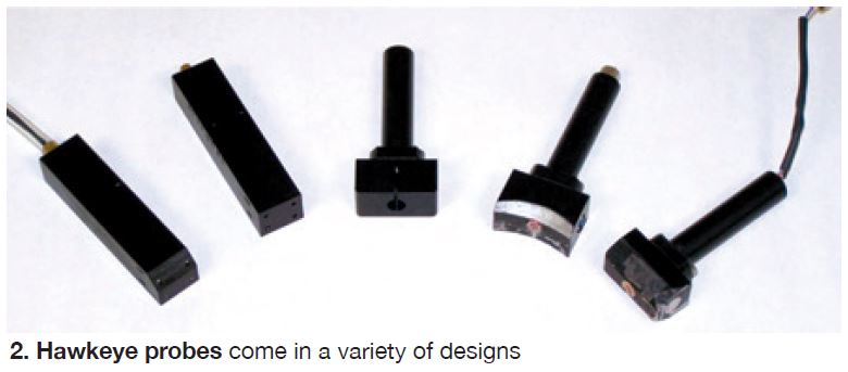
TesTex’s initial use of BFET centered on two types of probes, Hawkeye and Hawkeye DP (deep penetrating). The Hawkeye probe can penetrate up to 0.250 in. into the surface, the Hawkeye DP up to 0.375 in. The probes, traditionally hand-held (Fig 2), are in wide and varied use today. Probe surfaces can be machined to match required geometries (for example, a specific radius for tube and pipe welds), and multiple probes can be rigged for large areas.
TesTex has used this technology to inspect deaerators, piping, tube stubs, drums, distillation columns, dryers, heat exchanger shells, and other pressure vessels. All data are viewed in real time and recorded.
360-deg BFET
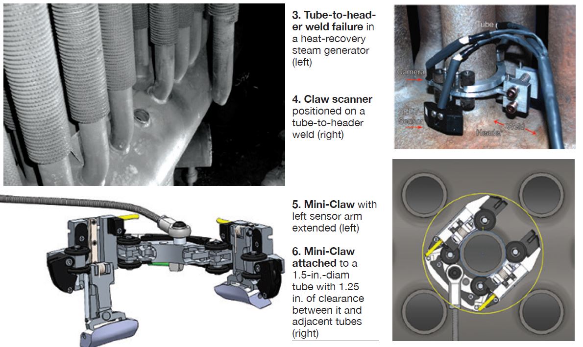
A major issue for both ageing and newer HRSGs is tube-to-header cracking and potential failure (Fig 3), experienced largely through leaks at the tube-side toe of the weld. But this occurs in a very congested, tightly spaced environment. Traditional inspection methods, such as magnetic particle (MT) and others, can only reach the exposed 180 deg—at best.
“It can be used anywhere an owner/operator suspects cracking within 0.25 in. of a surface,” notes Gowatski. “High-pressure superheaters and reheaters are particularly vulnerable due to ongoing unit cycling.”
TesTex developed the BFET, and in collaboration with EPRI, various tools for its application on HRSGs. One of these is the Claw (Fig 4).
With the Claw, BFET probes and cameras are placed on the welds using a C-clamp housing that attaches to the tube. Once attached, the assembly moves circumferentially around the weld examining for cracking, lack of fusion, porosity, and other defects. This technology detects surface cracks, as well as subsurface cracking within 0.250 in. of the surface.
A feature of the technology is that no surface preparation is required, and the inspection covers the entire 360 degrees of the weld. For most competing technologies, surface preparation can be difficult and time-consuming. Plus, radiography requires personnel evacuation from the area.
Says Gowatski, “Quality readings can be acquired through coatings such as paint, epoxy, and rubber. Uniform scale and rust do not present problems either. However, coal ash deposits, rough, uneven, or repaired welds, and pitted surfaces can present challenges. But they do not preclude successful use of BFET,” he explains.
The BFET probes ride along the contour of the tube-to-header weld and cameras monitor and record the entire process. But the significant achievement is investigation of the entire circumference. Even when a second technology is used for verification, this is normally limited to the 180-deg exposed area, limited by accessibility.
Another feature is the ability to eliminate liftoff (and/or probe wobble) and noise from the signal. As Gowatski explains, “There are two components of the BFET signal that we view, Asin and Acos. To have a clean signal without noise, the angle that we view is rotated and changed to put most of the noise on the Acos signal. By doing this, any cracks or small inclusions are shown prominently in the Asin signal.”
Claw technology is being used to detect fatigue cracking and other issues in headers with diameters from 4 to 14 in., and in tubes of 1.5, 1.75, 2.0, and 2.25 in. diameter.
Both the Claw and the new Mini-Claw (Fig 5) can check header welds on tubes with bends above or below the header. The latter is designed specifically for 1.5-in.-diam tubes and with extremely tight clearances between adjacent tubes—down to 1.25 in. (Fig 6). It has now been used successfully on multiple HRSGs.
Detect and record
With both the Claw and Mini-Claw, the balanced-field electromagnetic technique waveform is displayed in five different windows (Fig 7). The bottom right window shows the raw data, the bottom left the data processed. The two lines in the bottom two windows show the results from each sensor. The top line is from Sensor1, the bottom line from Sensor 2.
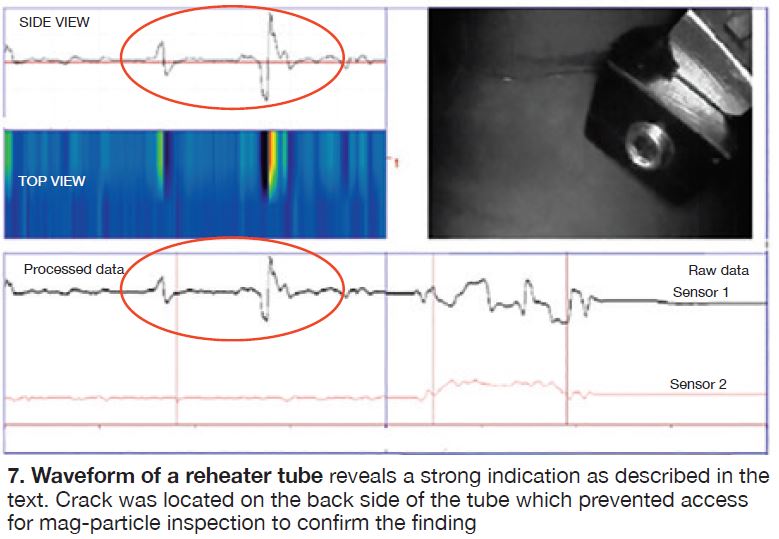
The middle left window is a simulated C-scan, the top left window a zoomed-in view of the data from the second sensor. The top right window shows a capture using the on-board camera.
Turnaround
TesTex has become known for its innovation and quick turnaround without interfering with operations, based on an informal survey of users. The company’s 200-plus person global network, headquartered in Pittsburgh, works primarily from US offices in Philadelphia, Houston, New Orleans, Atlanta, Bakersfield, and South Bend, as well as from locations in Canada, Trinidad, the United Kingdom, France, and India.
For more information, visit www.testex-ndt.com. CCJ