

By Dewayne Gilreath and Christen Mancini, Hydro, Inc.
Segmental-ring (BB4) boiler-feed pumps (BFP) can be sensitive to external forces, hydraulic instability, and alignment. This case study reviews modifications implemented to reduce leakage, minimize wear, and mitigate balance-device-driven vibration.
The boiler-feed system is the heart of the steam cycle, supplying feedwater to the HRSG for steam generation. Many combined-cycle facilities use high-energy segmental-ring (BB4) pumps for this critical service. Because the segmental-ring design relies on a large number of stacked components—without the stabilizing environment of a barrel—these pumps can be sensitive to external forces, hydraulic instability, and alignment issues. Given the pump’s direct impact on power generation, reliability is paramount.
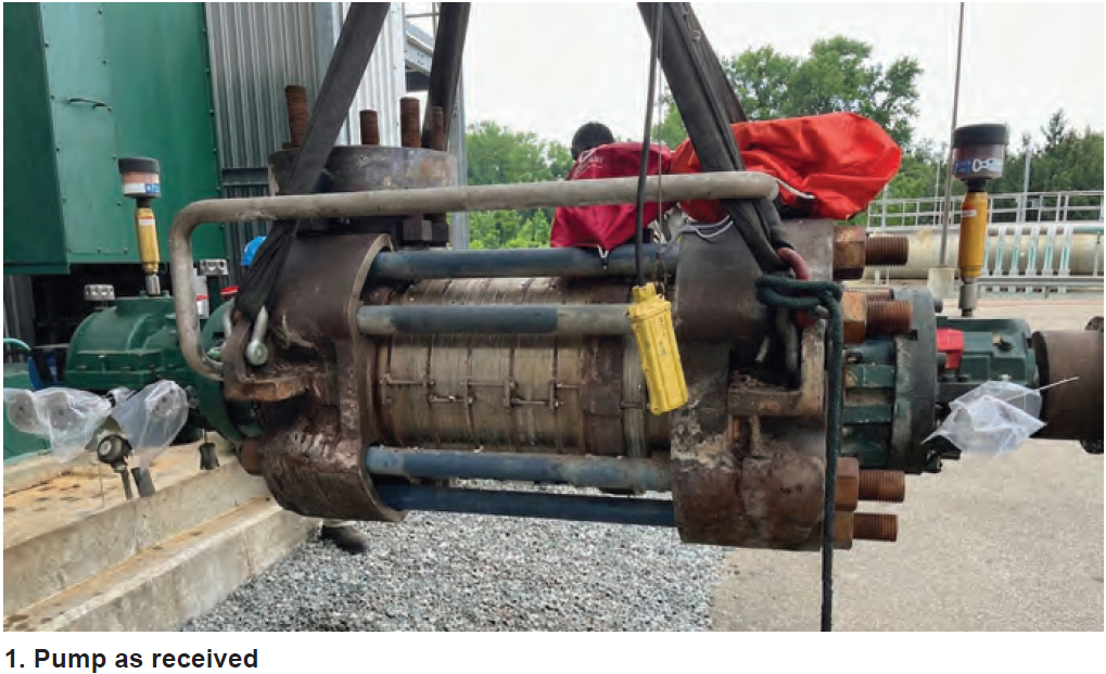
After experiencing high vibration, casing leakage, and other indicators of poor performance early in service, a combined-cycle owner/operator (O/O) identified design vulnerabilities and pursued modifications to improve robustness and restore best-in-class tolerances. Working with Hydro’s Atlanta facility (Hydro South), the team implemented upgrades focused on three areas (Fig 1):
- Eliminating leakage paths
- Minimizing wear and restoring rotor stiffness
- Reducing axial shuttling and balance-device-driven vibration
Eliminating leakage paths
Casing leakage was attributed to a combination of insufficient O-ring compression, material limitations, and incomplete maintenance instructions. Maintaining an effective O-ring seal requires (1) an elastomer compatible with the pumped-fluid temperature and pressure and (2) groove geometry that delivers adequate compression to maintain contact at sealing surfaces and compensate for minor surface imperfections.
Inspection found the groove sealing the balance-line flange to the pump discharge head was too deep to achieve the required compression. The flange was machined to restore the appropriate groove depth. All O-rings were upgraded to AFLAS®, a high-performance fluoroelastomer suited for elevated temperature and corrosive environments.
A documentation and work-instruction gap also contributed to recurring leakage. The seal-housing liner—installed with an interference fit—must be removed to access and replace two wear rings and associated “hidden” O-rings in that location. Because the existing O&M manual did not include these steps, prior maintenance cycles had not addressed these components. As an additional safeguard, the seal-housing sealing area was overlaid with 309L stainless steel to mitigate corrosion that had developed as a result of leakage in this area.
Restoring rotor stiffness, reducing risk of wear
The next objective was to reduce drivers of premature wear throughout the pump. Close-clearance regions—such as wear-ring-to-impeller-hub clearances—act as water-lubricated bearings that provide rotor stiffness and damping. Maintaining these clearances helps preserve stability, particularly in segmental-ring designs with many stages and long, slender shafts.
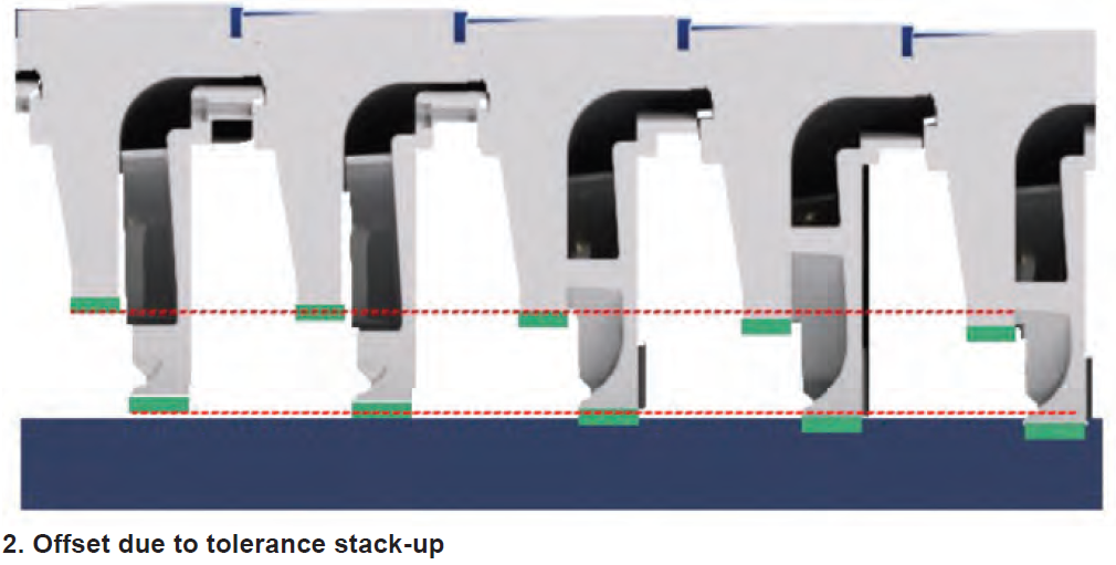
A foundational step in any multistage pump refurbishment is restoring components to best-in-class standards. Segmental-ring pumps demand experience and attention to detail during restoration and assembly. Tight control of bore geometry, face runout, and shaft straightness reduces the drivers of misalignment. Avoiding excessive fit-ups is also essential: because these pumps consist of stacked components, excessive register fits can accumulate and produce large offsets across the assembly (Fig 2).
To further reduce wear, wear surfaces were hardened using direct laser deposition (DLD). DLD provides a hard surface (typically around 55 HRC) while maintaining base-material ductility—unlike through-hardening, which can increase brittleness. In this upgrade, both the impeller hub and stationary wear rings were brought to similar hardness. With no hardness differential, there is no sacrificial component; if contact occurs, the components tend to “bounce” rather than wear, extending service life.
Another wear driver was identified at the interface between the last-stage impeller and the balance device. The original configuration left a gap between the last-stage impeller and the rotating balance sleeve. Without a positive stop to prevent outboard movement, the impeller could shuttle axially and contact the balance device and outboard diffuser face, accelerating wear. A set screw was added to the impeller hub to limit outboard movement and prevent contact.
Finally, several assembly practices were implemented to reduce risk and improve alignment:
- Chroming was applied to the impeller and balance-sleeve shaft fits to reduce galling risk during assembly (long, interference-fit bores are particularly susceptible).
- The pump was assembled in the vertical orientation to reduce the register-fit stack-up that can occur with horizontal assembly.
- Cold alignment between motor and pump was re-evaluated versus original specifications to better account for thermal growth and achieve proper hot alignment.
Reducing balance-device-driven vibration
With leakage and wear addressed, the final focus area was high vibration. Two drivers were identified within the balance device design and operation:
- Propensity for axial thrust reversals
- Fluid swirl in the balance-drum-to-sleeve clearance
Both contributed to elevated subsynchronous vibration.
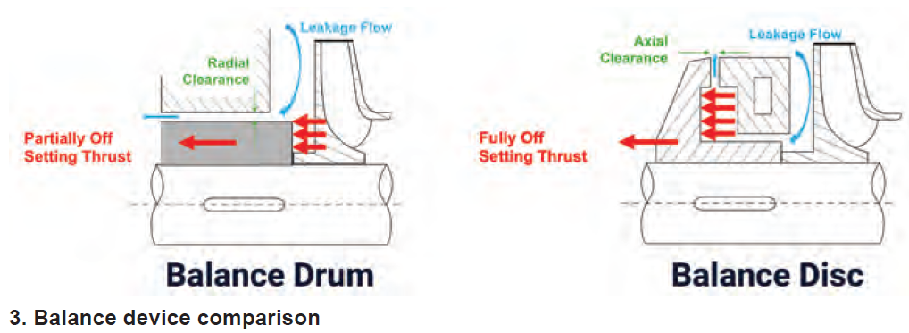
One reason the pump was susceptible is that it uses a straight balance drum rather than a flanged balance disk. The balance device reduces axial thrust during operation, lowering thrust-bearing load. A flanged balance disk, with both axial and radial clearances, is generally a self-compensating design capable of balancing axial thrust across operating points. A straight balance drum, by contrast, typically balances thrust at only one operating point (Fig 3).
Balance-drum sizing is based on total axial thrust from pressure acting on impeller hubs, which depends on wear-ring diameters. If wear-ring diameters change, residual axial thrust changes. During standard refurbishment, wear-ring clearances are often renewed by skim cutting the impeller hub and/or stationary wear-ring locating bore to remove damage, then installing a new wear ring sized to restore the intended clearance. This approach can result in varying wear-ring diameters across stages, depending on how much machining was required.
In this case, wear-ring diameter changes were sufficient to disrupt the intended residual axial-thrust balance. Axial thrust could also be affected by hydraulic instability at the impeller discharge when operating away from best efficiency point (BEP). Off-BEP operation can introduce intermittent, unpredictable swirl that increases the likelihood of axial thrust reversals—detrimental to bearing and seal life. To reduce this risk, Hydro South re-established not only design clearances, but also preserved the original design diameters of wear components.
The last concern was evidence of fluid swirl in the balance-device clearance. It was suspected that the as-installed running position had been adjusted during shop testing to reduce vibration, but that running position was not documented. Two flow breaks were added to the stationary balance drum to disrupt swirl, reduce subsynchronous vibration, and stabilize operation.

Final thoughts
Hydro South has upgraded three of the end user’s BFPs using the modifications outlined above and expects to complete the remaining pumps over the next several years (Fig 4). The improved operating behavior and reduction in vibration demonstrate that chronic instability in segmental-ring designs is not inevitable.
By going beyond standard repair scopes and applying targeted design and process upgrades, users can reclaim reliability in these critical assets—reducing risk to both safety and unit availability. CCJ


