

Stack dampers are simple on paper yet pivotal in practice. If they do not open cleanly at light-off, exhaust flow can choke, startup timelines slip, and HRSG parts see higher thermal stress. If they leak or stick during shutdown, stored heat bleeds away and the next start begins colder. In ISO-driven markets where starts and ramps are scheduled, these minutes and degrees translate to cost and wear. The points below adapted from SVI Bremco field experience, target fewer holds, more repeatable starts, and lower pressure-part fatigue.
What stack dampers do during a start
In a normal sequence the damper should offer minimal resistance as turbine exhaust moves from near zero to full flow, then seal effectively during shutdown and layup to retain heat. When travel is incomplete or inconsistent, two penalties follow: longer time to temperature and uneven heat delivery to upstream HRSG surfaces, which increases tube and header gradients. Reliability depends on reaching full open on cue, sealing when commanded, and repeating stroke time predictably so operators can coordinate purge, light-off, and warm-up logic.
Why delays matter in cycling
Frequent starts drive fatigue on equipment often designed for steadier duty. Late starts use more fuel, deepen temperature non-uniformity, and accelerate wear. Dampers are not the only factor in slow starts, but they directly control how heat is retained and released from cycle to cycle, so weaknesses show up quickly in plant performance.
Failure mechanisms
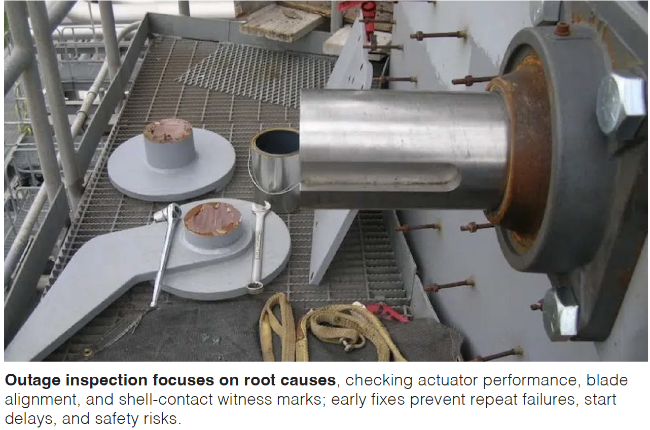
Most damper issues trace to the drive train and alignment. Marginal power, tired gearboxes, worn seals, or contaminated pneumatics cause partial strokes or stalls. Even small losses in torque or pressure can halt motion as exhaust backpressure rises. Misaligned or racked blades then add drag against the shell or stiffeners. Witness marks on the liner, shiny rubs, and uneven seal wear are common clues. The added friction loads the actuator, stretches stroke time, and evolves into repeated start holds. Misalignment seldom locks a damper immediately; it produces slow, inconsistent motion that increases actuator stress and erodes sequence predictability, leading to more manual intervention and occasional aborts when permissives are missed.
Design choices that reduce startup pain
Good design and installation make dampers more tolerant of dirty air, icing, and thermal growth. A fail-open configuration, where it fits the safety case and local codes, prevents exhaust restriction on loss of motive power. Weighted assist that allows opening at very low differential pressure, often near one inch of water column, reduces the risk that early exhaust meets a partially closed blade. Stiff, square frames with true hinge lines and positive stops help keep blades parallel to the shell. Allowances for thermal growth at anchors and hinges, supported by high-temperature bushings or bearings, accommodate slight misalignment without binding. Drives and linkages should be laid out for easy lubrication, seal replacement, and limit-switch adjustment so a cold start does not reveal a sticky mechanism.
Controls and proof that help operators
Instrumentation and permissives matter as much as mechanics. Use independent open and closed limit switches plus an analog position transmitter to trend stroke time and end-of-travel margin. Build timing checks into the logic and alarm when the damper is slow to open or slow to close so degradation is caught before it becomes a start hold. Verify closure during layup to preserve heat and moisture control. Adjust purge, light-off, and ramp permissives seasonally to account for winter conditions when lubricants stiffen and seals contract.
Commissioning and acceptance checks
Before turning a new or refurbished damper over to operations, record the measurements that anchor future comparisons. Measure stroke time for opening and closing at ambient conditions and again after the stack is hot. Document drive torque or actuator pressure at end of travel with margin noted. Check blade-to-shell clearances at several positions, verify any specified leakage rate, and store limit-switch set points along with the analog zero and span in the DCS change log.
Cut downtime
A short maintenance routine prevents the slow creep toward unreliable starts. During outages, verify frame squareness, re-shim hinges, replace worn bushings, clean and re-grease linkages with high-temperature lubricant, and re-set limit switches. Confirm torque switch or regulator settings against the acceptance record. Before return to service, run a cold functional test to measure stroke time and smoothness, then verify again hot after several hours online and watch for drift as the frame grows. In service, trend analog position versus command to catch slowing movement. Log minutes from open command to open proved as a KPI and investigate increases. After nuisance holds, check actuator output pressure or current under load and inspect for new rubs or witness marks.
Planning and installation tips
Schedule discipline lowers critical-path risk. Prefabricate where possible, using pre-assembled frames and access platforms to reduce on-stack time. Coordinate staggered shifts with HRSG, burner, and stack teams so damper work does not block other crafts. Plan rigging and scaffolding early to secure temporary access and avoid conflicts with SCR or liner activities. CCJ


