

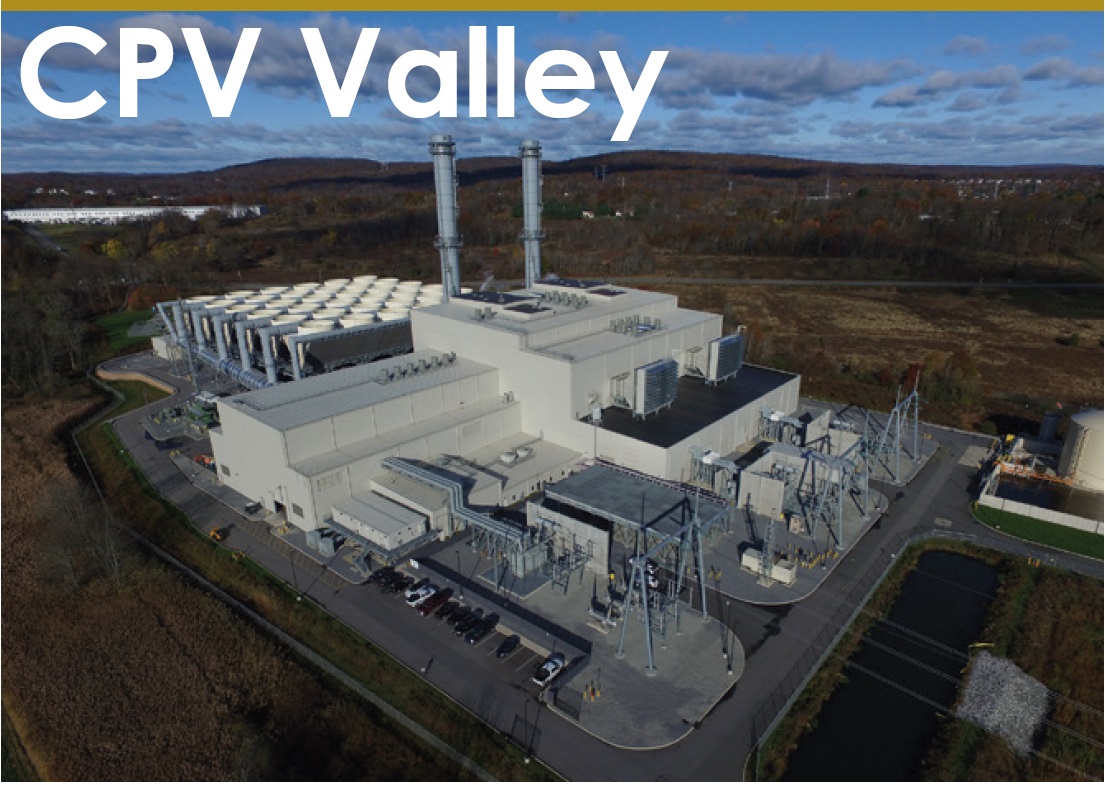
CPV Valley Energy Center
Owned by CPV/Diamond Generating Corp
Managed by Competitive Power Ventures
Operated by DGC Operations LLC680 MW, gas-fired 2 × 1 SGT6-5000-powered combined cycle, located in Middletown, NY
Plant manager: Michael Baier
Overcoming unique challenges to optimize ACC performance
Challenge. At first glance, the air-cooled condenser (ACC) at Valley Energy Center (VEC) appeared to operate efficiently, as designers intended. However, proactive staff analysis revealed performance-robbing subcooling, despite use of a second vacuum pump to compensate for air ingress.
Solution. VEC worked with SPG Dry Cooling to survey the ACC, identify leaks, and perform corrective measures; however, the subcooling remained. Further investigation revealed that increased air flow across the heat-exchanger bundles, paired with slight air ingress, was driving the subcooling anomaly. Although the system’s design backpressure, temperature, and steam load were in sync, more fans than required were operating. Further investigative work, found that the DCS logic prevented the fans from turning off to counteract the subcooling.
DCS logic. The ACC was operating at 2.0 in. Hg Abs, but the deadband within the logic required the pressure to reach 1.91 in. for 10 minutes to allow the control logic to adjust fan steps and reduce air flow. Several things were found that did not permit the ACC to drop to the required pressure for the prescribed duration, including the following:
- The vacuum system was designed according to specifications developed by the Heat Exchange Institute for ACCs, with a minimum design suction pressure of 1.0 in. Hg Abs. The steam path through an ACC is several hundred feet long, and the associated pressure drop can range from 0.5 to 1.0 in., putting the capacity of the vacuum system near the 2.0 in. setpoint (as measured at the ST exhaust).
- The air ingress persisted, spreading throughout the ACC, and limiting its cooling capacity. Conceptually, 1 ft³ of atmospheric air expands to 15 ft³ under vacuum, occupying volume intended for steam condensing.
The limitation of the vacuum system and persistent air ingress prevented the ACC from overcoming the deadband. It eliminated the control logic’s ability to adjust and optimize parasitic power alongside the backpressure. With the assistance of SPG, VEC made minor adjustments to the deadband and setpoint and reduced parasitic power by nearly 3 MW while maintaining the required backpressure. The improvement was achieved by turning multiple fans from full speed to half speed (reducing the required power per fan by seven-eighths) and eliminating the need to run a second vacuum pump. Additionally, VEC improved its overall heat rate by reducing subcooling and parasitic power consumption.
Note that the subcooling issue was unique to the time of year when ambient temperatures were between 35F and 75F. VEC operates approximately 5000 hours within this temperature range, resulting in a loss of approximately 15,000 MWh/yr prior to the new ACC logic implementation.
Results. VEC’s experience highlights the importance of investigating all aspects of ACC performance to optimize efficiency. As a result of this improvement, VEC will implement SPG’s remote performance monitoring system (ACC360) to maintain the realized results and continually improve the ACC system.
Project participants:
McKenzie Slauenwhite, plant engineer
Thomas Viertel, maintenance manager
Dave Engelman, operations manager
Efrain Morales, lead shift operator
Ernest Hill, lead shift operator
Bob Arraiz, lead IC&E technician
Daniel DeVito, IC&E technician
Closed-cooling-water-system upgrade saves money, improves safety
Challenge. If VEC lost station power, both pumps serving the closed cooling water (CCW) system would lose their power supply. Note that the power draw is too great to supply the pumps from the essential-services bus.
Were station power lost with the pumps in service, the flow of water to the steam-turbine lube-oil cooler (LOC) would stop. To mitigate this risk, a diaphragm pump was installed to maintain the required lube-oil temperature for turning-gear operation.
However, a challenge associated with the diaphragm pump is the amount of plant air required for its operation. Plus, the plant air compressors also are not on the essential services bus, which meant VEC would have to rent a diesel-powered air compressor during loss-of-power events.
Plus, plus, acquiring a diesel-powered compressor in timely fashion during an unexpected loss of station power is less than ideal for a rapid and guaranteed response. Finally, the diaphragm pump’s discharge flow is less than that required by the LOC to meet all possible needs.
Solution. Staff specified a centrifugal pump that maximizes CCW flow through the LOC to assure oil temperature can be maintained as necessary. A spare breaker on the essential-services bus met the power requirement of the centrifugal pump’s motor. Plant verified operation of the new pump during commissioning by using power supplied by the site’s emergency diesel/generator.
Additionally, the CCW discharge lines from the steam turbine’s LOC were tapped and valves were installed in the pump’s discharge and suction connections. Limit switches were added to the valves and brought into the DCS. The plant generated logic that allows the pump to be started from the DCS with the limit switches being a start permissive. Lastly, an HOA (hands off auto) switch was added to the pump’s motor breaker to allow manual operation.
Results:
- Increased safety: For example, less chance of steam-turbine damage caused by high lube-oil temperature.
- Eliminates the need to rent a diesel-driven air compressor on loss of electrical power.
- Fewer steps to put a pump in service during an emergency.
Project participants:
Thomas Viertel, maintenance manager
Bob Arraiz, lead IC&E technician
McKenzie Slauenwhite, plant engineer
Daniel DeVito, IC&E technician
Liam Collins, maintenance mechanic

