


The 13th annual meeting of the Air-Cooled Condenser Users Group (ACCUG) was held June 20 – 22 (2023) at Dominion Energy’s offices in Glen Allen (Richmond), Va. Strong international participation, interaction, and discussion enhanced the benefit of this event to all ACC owner/operators, service providers, and technical consultants worldwide.
The presentations discussed below, which focus on chemistry and corrosion, design and performance, and operation and maintenance, are available at acc-usersgroup.org. The next meeting of the ACCUG will take place in London this July. Registration is now open.
Chemistry and corrosion
Barry Dooley, Structural Integrity (UK) and conference co-chair, opened the conference with a backgrounder on ACC corrosion and cycle chemistry, stating that flow-accelerated corrosion (FAC) damage to ACCs is the same worldwide with all chemistries and plant types. This led to a discussion of global ACC inspections and common indicators of both single- and two-phase FAC, and a review of the phase transition zone in the LP steam turbine.
Dooley included details on corrosion damage and analysis, and a reference to document ACC.01, Guideline for internal inspection of air-cooled condensers, available at no cost on the user group’s website.
He concluded with an update on film-forming substances, and various technical guidance documents for plants with ACCs, available at www.iapws.org, and also free of charge.
Andy Howell, EPRI and conference co-chair, then examined ACC steam-side finned-tube corrosion downstream of tube entries. He focused on “new information, and a new investigation.”
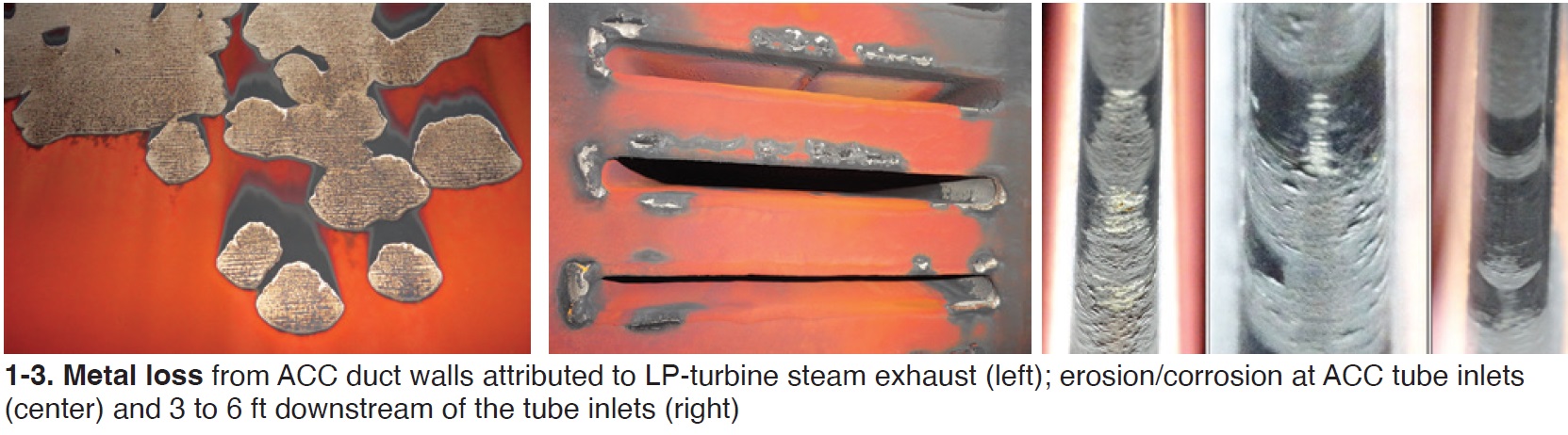
Howell began with erosion and corrosion of carbon steel in the LP turbine exhaust contributing iron oxide to the condensate, which would impact the surface of the ACC heat exchanger tubing (Fig 1).
More evidence of metal loss typically is found in the ACC steam distribution upper duct and at the tube entries (Fig 2). Metal-loss drivers are velocity and corrosion. At the tube entries, turbulence (velocity) is the highest, and the initial steam condensate is the most corrosive (lower pH).
Observations in 2022 identified metal loss downstream of the tube entry (Fig 3). This is the new information and investigation. Previously, industry focus was on the tube-entry area, and downstream corrosion had not been widely investigated or reported.
So, what are the implications of this down-tube corrosion? According to Howell, investigations are important because:
- This may be a major source of iron transport to the steam cycle.
- There is potential for tube leaks (air in-leakage).
- Investigations will help clarify whether all ACCs are susceptible and may provide more opportunities to reduce metals transport throughout the steam cycle.
Dooley then returned with a detailed look at film-forming substances, focusing on the latest international activities. For more on this topic, see FFS: Sixth International Conference, CCJ No. 75, p 75.
Sam Dunning, Virginia City Hybrid Energy Center, next offered a plant experience report on air in-leakage. Dominion Virginia Power’s VCHEC features two circulating fluidized-bed boilers and one 610-MW turbine/generator, commissioned in 2012. Fuels are waste coal and biomass.
The air-cooled condenser, by SPG Dry Cooling (formerly SPX), contains 10 streets of six bays each, with 36-ft-diam fans. Steam jet air ejectors remove non-condensable gasses from the ACC. Hogging ejectors are used to evacuate the ACC and dual-stage holding ejectors are used for normal operations.
Following a 2021 outage, VCHEC was dispatched to full load. Operators noticed that when switching from hoggers to holding ejectors, backpressure was not maintained. Hoggers were returned to service.
Typical air in-leakage indicators suggested a major leak in the ACC. The energy center was derated by 200 MW for two days and by 100 MW for five days. Troubleshooting, including use of all typical methods of leak detection, met with no success.
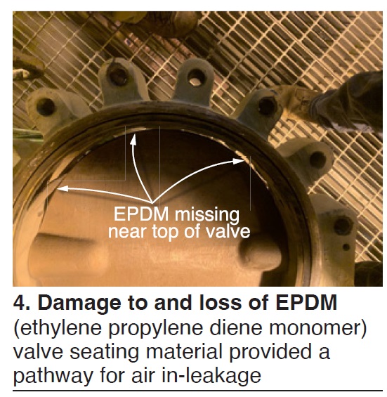
Then, a large leak was found in the hogging-ejector isolation valves. It allowed air to be pulled back into the discharge side of the out-of-service hoggers. Said Dunning, “inspection of the valve internals showed the rubber (EPDM) seated valves had lost more than half of their seals” (Fig 4). The rubber had become brittle and the adhesive used to hold the seal in place had deteriorated. Other valves were checked and all were experiencing the same failures.
Valves were replaced in-kind for operations, and later replaced with metal-seated ones.
Dunning’s observation and recommendation: The seat design of the rubber-lined seal limits the rating level of vacuum valves. High-performance butterfly, including triple offset styles, should be considered. He added that “if rubber-seated valves are currently in vacuum service, periodic inspections should be conducted more frequently as the valves age.”
Design and performance
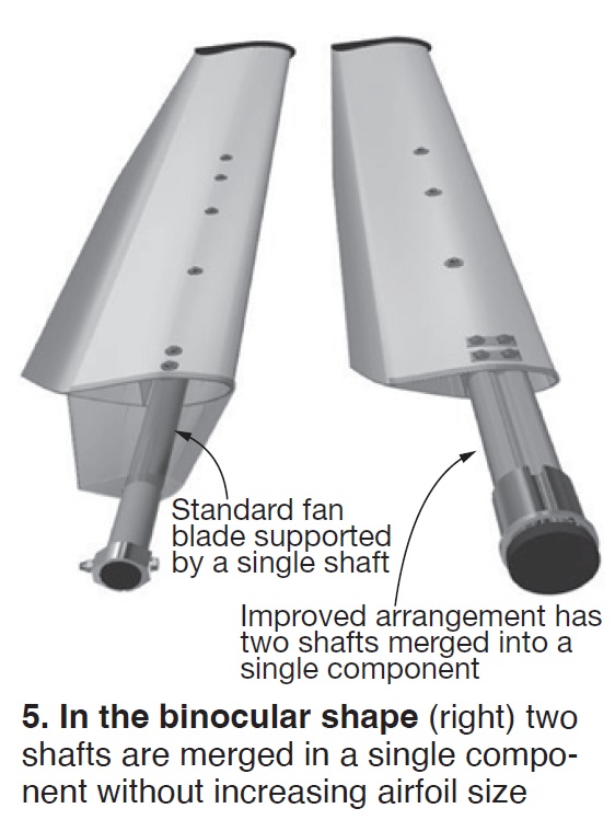
Carlo Gallina, Cofimco (Italy), presented FRP-carbon twin shaft for axial fan blades. Said Gallina, “research and experience showed the need for an improved shaft to connect the blade airfoils to the hub. This led to the pultruded FRP-carbon twin shaft to improve the blade load capacity of large fans in both ACCs and cooling towers.”
He reviewed the basics. Lift must be generated for each blade, but varies because of aerodynamic disturbances—including mechanical obstacles (walkways, etc), wind gusts, and fan location within the ACC. Bending moment and lift are transferred to the hub, drive system, and structure, all influenced by the varying loads.
“Therefore,” he explained, “the blade connection to the hub must be strong enough to withstand high loads generated at the shaft.”
Rigid solutions transmit loads to the structure and can cause vibrations. “Using pultruded FRP-carbon shafts gives the blades suitable flexibility, and reduces vibration. Plus, the high strength of carbon limits blade deflection.” Plus, plus, the natural frequency of these blades is far from typical fan forcing frequencies.
Next, Gallina introduced the Cofimco twin shaft for axial fan blades featuring a “binocular shape” (Fig 5, right). He then reviewed full details of work at Cofimco’s test rig complex in Italy. Conclusions:
- The twin-shaft blades can withstand severe duty points and manage high, abrupt loads.
- Blades generally can be operated from zero to 100% speed when driven by a VFD.
- Vibrations and loads introduced to the structure are greatly reduced.
Huub Hubregtse, ACC Team (The Netherlands), discussed Common performance problems for ACCs. “In general,” he began, “there is a lack of technical knowledge by operators, and many ACCs have performance problems, especially in summer. Not all operators have enough knowledge of the processes to analyze the system.”
He outlined and discussed the primary impacts on performance:
- Fans in respect to air flow and static pressure.
- Recirculation of hot air.
- Fouling.
- Steam distribution in heat exchangers.
- Leaks.
- Noise (indirectly).
Static pressure reduces air flow and increases motor power requirements. He discussed fan measurement criteria for air flow, static pressure, and absorbed power.
“Recirculation means hot air from the top is sucked down to the fan inlet, resulting in warmer air for cooling,” he explained. The main cause is the difference in suction pressure at the fan inlet and the pressure at the outlet of the ACC. This can be caused by a nearby building, wind, or other factors. To check this, he suggests measuring air temperature in the plenum and air temperature at a distance.
“Fouling from dust, seeds, and insects can obstruct the space between the tube fins, resulting in higher static pressure and less air flow,” he continued. Most fouling can be removed with high-pressure washing (1300 to 1600 psig). Other fouling can be difficult and require blasting with sodium bicarbonate or similar method. “The performance impact of cleaning can be enormous,” he offered.
Hubregtse continued: Steam flow through the ACC heat exchangers is controlled by the small (15 mbar) pressure difference between inlet and outlet. Flow reduction causes can be fouling, vacuum pumps, or layout of the suction piping. Testing with thermal imaging should reveal the problems.
Imaging can show low pressure differentials in the middle of the tubes, for example. The suction processes will take vapor/steam before they take air. If there is a leak, air can penetrate the system, blanketing the inside of the finned tubes. A simple vacuum drop test can indicate leak rate.
But finding the leak can be difficult. “The most common and reliable way to find leaks is to spray helium gas near a suspect location and test the ACC for helium in real time. Helium testing can be expensive (and time-consuming), but is reliable,” he explained.
Although noise is not directly related to performance, “some operators reduce the speed of the fan when noise is a concern,” he noted. If this occurs, “the blade angle has to be increased to compensate for the loss of air flow.” One danger is that the fan can go into stall, reducing the air flow.
Keith Paul, EPRI, followed with Infrared drone inspection of an air-cooled condenser to analyze heat distribution. The subject site was New York Power Authority’s Zeltmann Power Project, a 576-MW, 2 × 1 7F-powered combined cycle in Astoria, NY, commissioned in 2005.
Before the site visit, drone calibration runs were conducted at Evapco Test Labs in Maryland. “We ran the same drone, tested camera resolution and distances, and tested air in-leakage detection with intentional in-leakage.”
His conclusion: “Based on our experience at Zeltmann, and at Evapco’s test lab, we cannot say that drone infrared inspections provide definitive leak-detection services. This is still a work in progress.” The site switched to still cameras.
On the positive side, initial results at Zeltmann allowed the plant to focus on specific sections for possible repairs in an upcoming outage.
“EPRI is now developing a test methodology to use acoustic cameras mounted on a drone to inspect air-cooled condensers,” Paul explained. This is based on success with handheld acoustic cameras. This ongoing drone work is a potentially strong time-saving technique.
Hector Moctezuma, Valia Energía (Mexico), offered an Update on a hybrid cooling retrofit installation, first presented to ACCUG in 2014. He spoke first about the plants in his country.
“Plants are often not able to reach maximum output during summer due to high steam-turbine backpressure from the main condenser, which limits use of duct burners and sometimes means reducing CT output to avoid a steam-turbine trip,” he said.
More specifically, “This significant power output reduction is due to ACC under performance in summer and with windy conditions.” ACCs have also experienced physical degradation through the years, mainly severe fouling and tube damage.
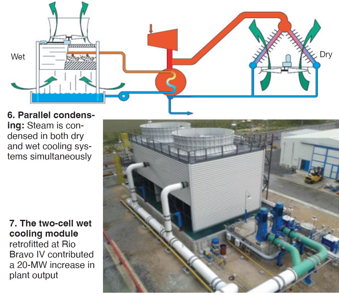
“With the help of SPIG USA, a parallel condensing system (PCS) was chosen in which exhaust steam is simultaneously condensed in both a wet evaporative and the existing dry cooling system” (Fig 6).
“The goal is to remove the steam-turbine backpressure limitation during all periods with ambient temperature higher than 86F (1000 hours per year) by adding enough wet cooling capacity to the existing 32-cell ACC.” The design considers local water limitations.
The speaker reviewed results for the nominal 500-MW Unit IV at Rio Bravo Energy Park after addition of the wet cooling module in Fig 7. The highlights:
- Elimination of the backpressure limitation, with a significant sustained improvement of up to 80 mBar (2.36 in. Hg).
- Power output increase of 20 MW attributed to the condenser pressure reduction and ability to increase condenser load.
- Heat-rate improvement due to lower condenser pressure (lower backpressure on steam turbine).
- Power-consumption increase by auxiliaries of about 500 kW for the cooling-water pumps, blowdown and makeup pumps, and cooling-tower fans.
This gives “consistent and repeatable operational reliability under adverse summer conditions after nine years of operation,” he stated.
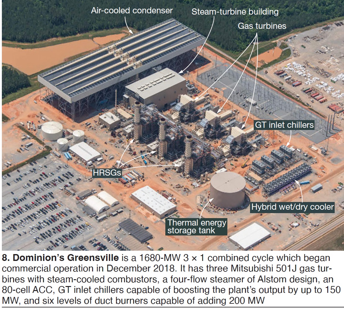
György Budik, MVM EGI (Hungary), presented on the Hybrid delugable cooler in Dominion’s Greensville CCPP which satisfies the facility’s auxiliary cooling needs using a 50/50 mixture of glycol and demin water. The cooler is located at the opposite end of the plant from the 80-cell ACC (Fig 8).
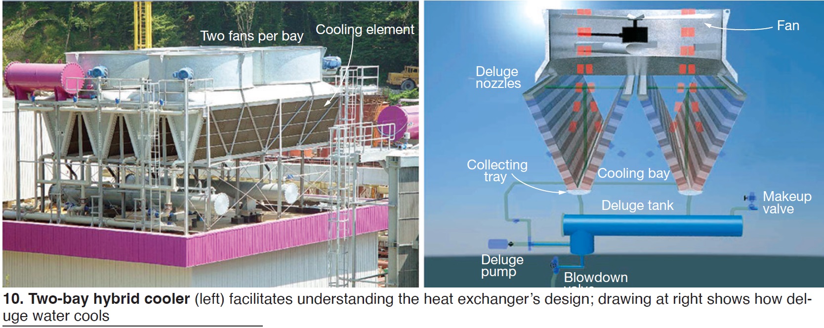
Hybrid wet/dry coolers like Greensville’s (Fig 9), Budik explained, “offer a dramatic reduction in cooler size relative to all-dry coolers, and, therefore, a significant reduction in civil and maintenance work.” The speaker reviewed some delugable systems installed by his company, including the first such units, which were installed in Iran.
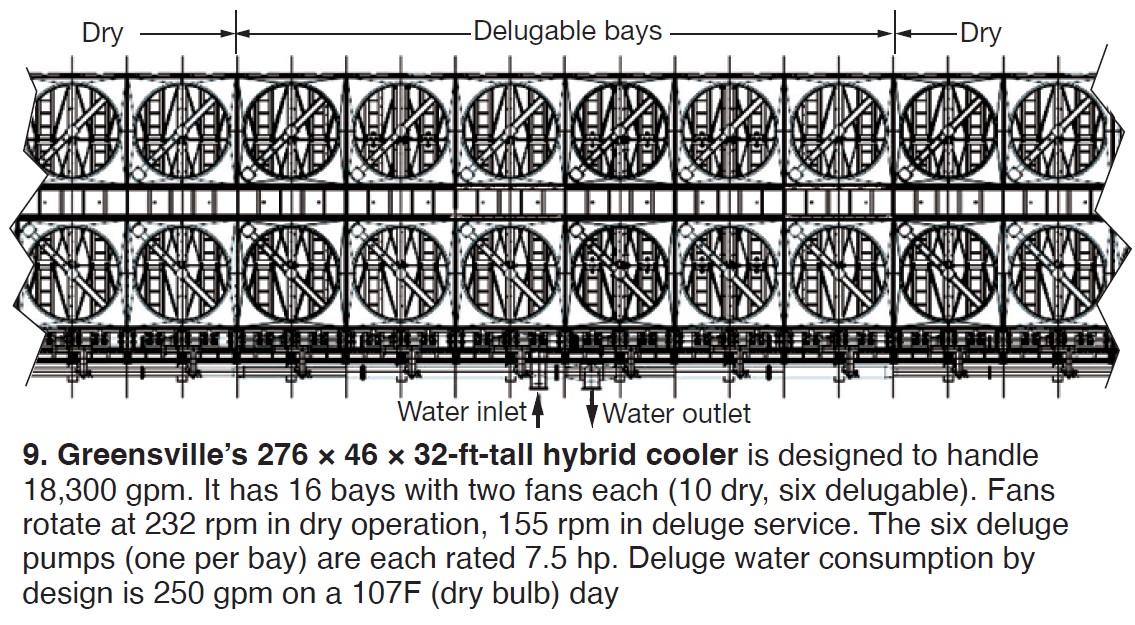
The auxiliary cooler consists of 16 modules arranged side by side, the first five (left side) and the last five (right side) are dry, the remaining six (bays 6 – 11) are capable of deluge service.
Bays have two cooling modules, each with two 12-m-long aluminum cooling elements, best illustrated in the Fig 10 photo. The cooling modules serving all bays are connected in parallel to a common inlet and outlet manifold.
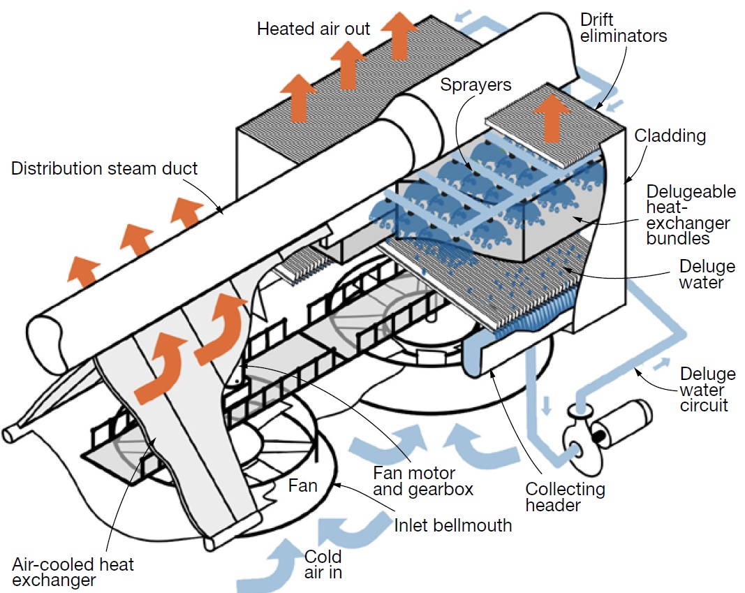
In the deluging bays, sprinkler pipes are installed at the top of the cooling elements, providing a continuous downward flow of water on the external surfaces of the heat exchangers. The Fig 10 illustration explains this.
The operating principle of the deluge system is that partial evaporation of the deluge water keeps relatively cold the rest of the water on the heat-transfer surface, thereby providing additional cooling.
Deluge water is supplied to the heat exchangers from the tank shown in the figure. Water not evaporated is collected in a trough at the bottom of the module. The trough drains to the deluge water tank. A makeup line keeps the amount of water in the system constant. Note that water of good quality is required for makeup, with first-pass RO product acceptable.
Motors driving the deluge pumps are equipped with variable-frequency drives. Operation of the deluge system is not recommended at ambient temperatures lower than 98F, all-dry operation providing sufficient cooling. Use of the deluge system would result in unnecessary water loss from drift, evaporation, and blowdown.
At temperatures above 98F, the number of fans operating in deluge modules are governed according to the following control steps:
- Step 0: standby, steady state.
- 1: 12 VFD-controlled fans in bays 6-11 start simultaneously.
- 2: Front-side fans in bays 1-5 and 12-16 start.
- 3: Dummy step.
- 4: Remaining fans in bays 1-5 and 12-16 start.
- 5: Deluging starts in two bays.
- 6: Deluging expanded to four bays.
- 7: Deluging expanded to all six bays (Nos. 6-11).
Note that with Step 7 actuated, design performance conditions are achieved with one fan out of operation.
Next objective for the new hybrid cooling technology demonstrated at Greensville likely is its use in conjunction with dry cooling systems for combined-cycle plants (sidebar). The deluge ACC is touted by its EU sponsors as being the most efficient dry-cooling solution for high peak ambient temperatures. Plus, it is said to resist adverse ambient conditions such as high-speed winds and hot air recirculation.
Other benefits include less auxiliary power consumption, smaller footprint, and lower construction costs compared to dry-only systems. And less water consumption compared to all-wet systems.
ACC with deluge cooling: Not yet, but likely soon
Literature from Enexio Water Technologies GmbH touts Deluge ACC, described in the diagram, as the latest technological achievement in hybrid cooling, where the primary interest is in dry cooling, but where limited water resources are available for use during certain times of the year.
Recall that while dry cooling methods offer an order-of-magnitude reduction in cooling-water consumption compared to wet cooling, overall power-cycle efficiency generally is higher when wet cooling can be part of the solution.
Enexio is one of the consortium partners of the EU-funded Horizon 2020 research and innovation program called MinWaterCSP. Its goal is the development of cooling technologies and water management plans to reduce cooling-system water consumption by up to 95% relative to wet-only cooling systems.
Galebreaker Industrial’s Gary Mirsky presented CFD study of airflow and performance improvement potential. His example was a 2 × 1 plant rated at 578 MW (steam turbine output, 295 MW) commissioned in 2008.
The goal was to increase backpressure trip limits as part of a larger upgrade to increase both gas-turbine output and ACC heat rejection. Another objective: Mitigate wind effects on ACC performance.
The ACC is two units, each with three streets and five cells per street. There are buildings in the immediate area. The best performance solution was a combination of options with both perimeter and cruciform screens.
Operations and maintenance
Mike Owen then presented the latest ACC-related research activities at Stellenbosch University in South Africa. It is home to an active research group specializing in ACC and dry-cooling activities, and is a frequent participant at ACCUG events.
Topics this year included prediction of large-diameter axial-flow fan noise and performance, dynamic blade loading, modeling improvements, machine learning for performance monitoring, and fan drive-train dynamics.
Owen also covered specifics of operation and controls—including air-extraction valves, fan speed range and fan hardware, fan gearbox/motor/VFDs, two-stage air ejectors, drain pot, and pumps. Most of these items would be mentioned during the site tour of Greensville on the last day of the conference.
Jeff Petrillo, Dominion, introduced the group to the Greensville County Power Station with ACC lessons learned. He presented a site overview to familiarize those joining the tour with the facility’s layout and principal equipment. The latter included the following:
- 80-fan (VFD) ACC with 10 streets (five east, five west).
- One condensate receiver tank with two deaerators.
- Four liquid-ring vacuum pumps.
- Two two-stage steam-jet air ejectors.
- One drain pot with two pumps.
Jacques Muiyser, Howden Netherlands, presented ACC fan dynamics: Potential problems and solutions. The basis of this discussion: ACC fan blades and/or connection bolts can fail because of high dynamic loads. Muiyser discussed sources and consequences of dynamic/cyclical blade loads, and development work to confirm that a stronger hub design with a more rigid bolt-to-bolt connection can help avoid bolt failure from fatigue.
He began with a refresher course on blade dynamics and mechanical properties, also covering flow distortions attributed to obstructions and crosswinds before moving on to case studies.
In the first case study, owner/operators noticed isolated U-bolt failures at a site. Strain-gauge measurements revealed resonance at high fan speed. Performance measurements then showed the blade angle could be increased while reducing fan speed to avoid the failures while maintaining performance.
In the second case, recurring issues were blade separation at the leading edge, and blade clamping-bolt failures (straight bolts). For the blades, strength was corrected with additional laminate on the leading edge. The clamping bolt issues were corrected by adding a secondary hub ring, connecting all of the clamping pieces.
In Case Three, straight-bolt failures shortly after installation showed signs of failure, primarily at edge cell fans. Root cause was high dynamic loads attributed to winds and high-speed resonance. A modified hub ring was installed to reduce equivalent dynamic loads.
“The hub ring assembly has proven to be an excellent retrofit solution for sites with high dynamic loads. This solution has been tested on site and the design has been refined through testing in the laboratory and numerical simulations,” said Muiyser.
Edwin Houberg, Sumitomo Drive Technologies/Hansen Industrial Transmissions, introduced the Hansen M4ACC gearbox for forced-draft and the Hansen M5CT for induced-draft applications.
The first features mono-block housing, no external piping, and an integrated drywell to reduce leakage risk. One option is a patented mobile brake system to slow down and stop the gear unit during maintenance activities.
The M5CT is a “new right-angle industrial gearbox series dedicated to induced-draft cooling technology,” he explained. This features an extended bearing span with heavy-duty roller bearings for strong shaft support. Numerous instruments and accessories are available.
Jeff Ebert, Galebreaker, then discussed Mitigation of extreme high seasonal winds. His example was a 353-MW gas-fired powerplant in Saskatchewan, Canada, commissioned at the end of 2019. Seasonal winds there can blow at 19 m/s, reducing plant performance.
Galebreaker was asked to determine the best windscreen configuration, height, and solidity to resolve the performance issues.
Ebert described the evaluations and installation that was completed in April 2023.
Various options were considered and material was delivered in October 2022. This was Galebreaker’s first sloped-structure ACC project (Fig 11).
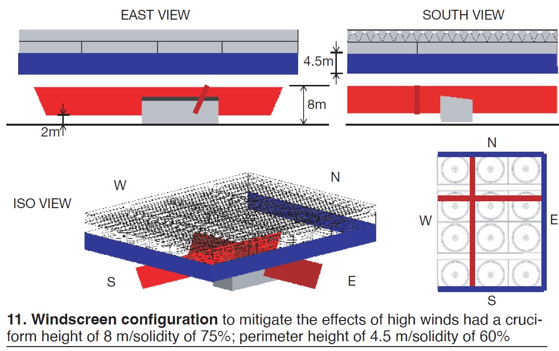
Various tubular products were added for structural support.
Hubregtse returned to discuss gearboxes for ACCs, listing these critical items to include in specifications:
- Fan shaft power.
- Power absorbed during worst conditions (during a storm, for example).
- Inverter installed, variable or direct.
- Service factor.
- Lubrication.
- Vibrations.
- Temperature range.
A standard service factor, usually between two and three, allows for vibrations, extreme conditions, startup power, and wear. This is also valid for gears, bearings, shafts, and housing.
He also covered thermal power (heat generated inside the gearbox), forces in gearbox, gearbox selection, lubrication, humidity in oil, vibrations, and deformations.


