

 Mike Hoogsteden, Advanced Turbine Support LLC’s director of field services reminded the large gathering of owner/operators at the company’s booth during the 2017 7F Users Group vendor fair, May 15-19 in San Antonio, about the importance of proper F-class turbine wheel inspections.
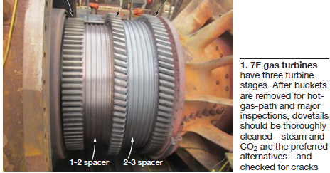
To increase the probability of detecting flaws of critical size, he recommended thoroughly cleaning dovetails after buckets are removed (Fig 1) for hot-gas-path (HGP) and major inspections. The preferred methods of preparing dovetails for inspection are steam cleaning or CO2 blasting.
The inspection technique proven to best detect wheel flaws, Hoogsteden said, is eddy-current array using specialty probes which allow technicians to scan a large area and collect data for analysis and characterization. He added that Advanced Turbine Support has worked with several vendors to optimize its inspection methods to best meet fleet needs.
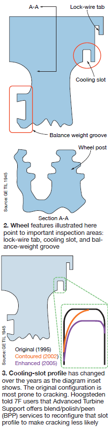
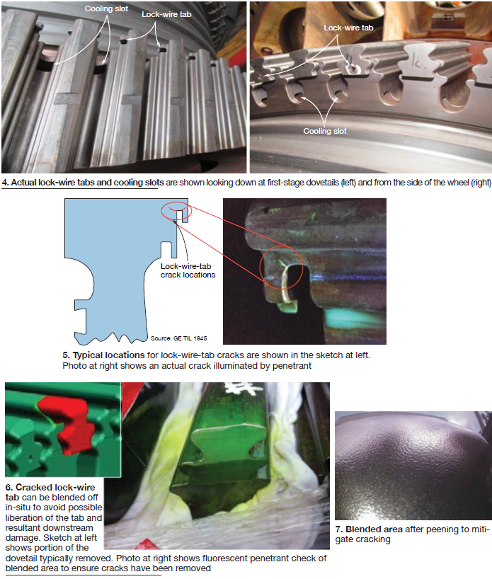
Cooling slots. Hoogsteden went on to say the company’s technicians have identified 16 cracks ranging from 0.04 to more than 2 in. in length propagating from first-stage cooling slots (original configuration) in 7F engines since 2013 (Figs 2 to 4). He added, “In 2017, three units were found to have conditions which condemned wheels and component replacement to enhance unit reliability and safe operation.”
Owner/operators of units with the original cooling-slot configuration can minimize the possibility of cracking, the field service director said, by way of a blend/polish/peen procedure that results in a component radius and compressive stress in accordance with best engineering practice. Fluorescent dye penetrant inspection is used to confirm the absence of indications.
Lock-wire tabs. Cracks propagating from the edges of first- and second-stage turbine-wheel lock-wire tabs are another concern (Fig 5). Typically, cracks in these locations are viewed as less critical than those in the cooling-slot area. Here’s why: An affected tab can be blended off in-situ (Figs 6 and 7). A caveat: If three or more consecutive tabs on a given wheel are cracked, tab removal is not an OEM-approved solution. That turbine disc would require engineering disposition and most likely would be condemned.
Background. The importance of turbine-wheel inspections should not come as a surprise to most 7F owner/operators; the subject has been a discussion topic at user meetings for two decades, or more. However, given the recent rash of retirements, the continual shuffling of personnel among plants, significant numbers of O&M personnel joining the staffs of 7F plants, etc, “refreshers” are important. No plant manager can ever assume “everyone knows this.”
Users might consider perusing the OEM’s library of Technical Information Letters (TIL) to gain the foundational knowledge required for objective decision-making. For example, the subject of wheel cracking in early 7F rotors is addressed in TIL 1945, “F-class Turbine Wheel Inspection and Maintenance Recommendations,” as well as in other GE documents.
Here are some take-aways from TIL 1945 pertinent to the foregoing discussion:
- Turbine buckets are retained axially by a snap-ring type of lock wire located in a machined groove passing through the buckets and turbine wheel. The portion of the wheel retaining the lock wire is known as the lock-wire tab.
- Cooling air is provided to first- and second-stage buckets via cooling slots at the bottom of the turbine-wheel dovetails.
- 7F turbine rotor discs are made of a high nickel alloy sensitive to surface imperfections. The high-stress/high-temperature operating environment is conducive to intergranular crack initiation and propagation.
- Rotors operating in regions of high ambient temperature and humidity, or where other corrosive conditions exist, have increased risk of crack initiation and propagation.
- A process of continual improvement has reduced the sensitivity of turbine rotor wheels to cracking, inoculating late-model engines against some of yesterday’s concerns.
- Rotors manufactured prior to 1997 did not have full shot-peen coverage of turbine wheels. Recall that shot peening leaves a residual compressive stress and decreases the risk of crack initiation—such as in the region of the dovetail slots. After 1996, all F-class turbine wheels shipped fully shot-peened.
- During operation, the intersection of the cooling slot and dovetail slot is subjected to high temperatures and tensile stresses caused by turbine bucket pull. The high temperatures and stresses, in conjunction with an adverse edge condition, have been known to initiate cracks in this location.
- Cracking has been found in several rotors at the balance-weight groove, initiating at an adverse edge condition (refer back to Fig 2) influenced by the balance-weight retention method and other variables. CCJ