

Ansaldo/PSM
PSM’s four-hour session at the 2019 501F Users Group meeting incorporated presentations on the vendor’s product line, combustion options, airfoils and upgrades, plant optimization, and rotor solutions, as well as other topics. The product portfolio was reviewed first. Highlights included the following:
-
- PSM said it can supply all hot-gas-path (HGP) parts for the 501F. The re-engineered, upgraded components are supported by an independent supply chain. No CIs are required for any of the company’s combustion parts, with a 32k CI/HGP interval an option.
- Flexible long-term agreements (LTAs) allow a term warranty using the owner’s inventory. A customer portal was launched at the end of 2018 to support all owner/operators with LTAs. Document management and easier access to technical expertise are two benefits.
- Rotor-repair and life-assessment services are offered, along with onsite disposition and machining. A seed rotor is available.
- The company reported having done more than 70 combustion conversions, claiming it is the only aftermarket provider of upgrades for output.
The PSM team next discussed the interchangeability of the company’s parts—both standard and upgraded—with original equipment, stating that all of the supplier’s hardware is set-wise compatible. A few examples presented were these:
Compressor. Replacements for all FD components.
Combustor. Full drop-in system or component replacement, gas only and dual fuel. FlameSheet™ is available for both the W501F and M501F.
Rotor swap with LTE, replacement disc fabrication, and improved bolting and belly-band design.
Turbine. All major components for the W501FC-FD2 and M501F3 models, plus the first three stages for the W501FD3 (fourth stage is in development). Also available: An improved static seal and inner support ring.
Exhaust. W501FC-FD2 drop-in cylinder (includes new manifold front flange); FC-FD2 drop-in manifold (available only with PSM exhaust cylinder).
Drop-in combustion-system experience was summarized in one slide. About 70 sets of pilot nozzles had been sold, the speaker said, with fleet leaders about 60k fired hours and 1500 fired starts. Total fleet experience was 1.9 million EBH.
For transition pieces, the numbers were more than 100 sets sold, fleet leaders at more than 60k fired hours and 1400 fired starts, and fleet experience at more than 2.4 million EBH.
Extended-turndown combustion baskets have been installed in more than 35 engines, with fleet leaders at 35k fired hours and more than 600 fired starts.
The numbers for support housings: More than 25 sets sold with fleet leaders at 33k fired hours and more than 600 fired starts.
Turndown solutions is always a hot topic at user-group meetings. PSM reported that for a nominal DLN equipped 501F, turndown to about 65% of rated output is possible without exceeding CO emissions of 10 ppm. AutoTune, in concert with the company’s part-load performance (PLP) option, could enable turndown to about 55% , while adding inlet bleed heat might lower that to 40%+. Retrofitting FlameSheet can get turndown into the 30s, and adding exhaust bleed makes a 20% number possible.
A big benefit of FlameSheet, in addition to extended turndown capability, is greater fuel flexibility compared to traditional OEM offerings. This is particularly beneficial both to plants burning shale gas and LNG, which may have a wide range of varying constituents, and to those with access to off-gases from industrial processes. FlameSheet can maintain emissions compliance while operating on fuels with up to 40% hydrogen and up to 40% C2.
Results from the first two installs of FlameSheet in 2015 at Eastman Chemical Co, Longview, Tex, were reviewed to confirm stated performance. The data:
-
- Turndown was confirmed to 40% of rated load with NOx emissions below 5 ppm at 40% and less than 7 ppm at 100%.
- CO was less than 9 ppm at 40% load and about 1 ppm at 100%.
- Part-load efficiency was measured at less than 120% of the full-load number; goal was 130%.
- Startup visual emissions were eliminated, reducing exceedance reporting by 200 reports annually.
Important: FlameSheet enables Eastman to keep its units operating year-round because of their increased turndown. Also, it gives the company the potential to burn waste fuel streams rich in hydrogen.
Recent field experience with the GTOP6 and the expected performance benefits of GTOP7 were reviewed. Recall that the components incorporated into the company’s GTOP6 (Gas Turbine Optimization Program) upgrade—roughly the equivalent of a Siemens FD3 upgrade for performance, but executed in a smaller scope—can have a maintenance interval of up to 32k/900 starts.
The GTOP6 fleet leader at the time of the 2019 meeting had operated for 19,500 factored fired hours and had 124 FF starts since the upgrade was completed in 2016, increasing combined-cycle output by about 40 MW. A borescope inspection revealed parts in excellent condition. Planned maintenance interval for the gas turbines serving this unit is 25k hours/900 starts, with a four-interval lifetime for all parts.
Performance of the coming GTOP7 bests that of the GTOP6 by a modest amount. For example, the 25k version of the former is expected to increase the simple-cycle output by 20 MW and reduce heat rate by 3.8% compared to a standard W501FD2 engine, while GTOP6 delivers 15 MW and 3.5% for GTOP6.
Extending the maintenance interval to 32k from 25k has a significant negative impact on performance. For GTOP6, opting for 32k hours reduces the output gain to 7 MW and drops the heat-rate benefit to 1.5%. For GTOP7, the loss in output is more severe, down to 8 MW from the 20 MW increase at 25k. The heat-rate benefit decreases from the 3.8% at 25k to 2.1%.
The plant optimization presentation focused on PSM’s FlexSuite™ offerings to help customers navigate the paradigm shift to faster starting (FlexStart), faster ramping (FlexRamp), etc. The speaker began by stating some of the challenges facing owners in today’s world of power operations.
Only a few years ago, he said, the goal for breaker closure on a simple-cycle unit might have been 27 minutes, today it is less than 10; the time to achieve full output was about 40 minutes for a large legacy frame like the 501FD2 to minimize life consumption of hot parts, now 15 minutes is the expectation.
In the rotor presentation, attendees were told PSM had completed eight F-class lifetime evaluations and had five F-class swaps under its belt. Two of the swaps involved 501Fs. During a 2016 swap PSM took possession of a rotor with a cracked torque tube. Incoming inspections were nominal, but NDE revealed a 2-ft through-wall crack and replacement of the torque tube was required. A root-cause investigation did not identify any structurally relevant pitting or other anomalies.
Another 501F rotor was pulled from service in 2017 because of an air separator issue. Onsite machining was unable to remove material hardened because of a rub and the rotor was sent to the shop. During the lifetime evaluation process, a compressor disc was found to have several discontinuities. The unit’s owner opted to install a seed rotor rather than extend the outage.
General Electric
GE’s third year of participation in the 501F Users Group’s annual Conference and Vendor Fair in 2019 focused on the following three key topics:
-
- Customer concerns regarding the OEM’s business—including its restructuring and creation of GE’s Gas Power organization.
- Results from the implementation of upgraded hot-gas-path (HGP) hardware at a combined cycle owned by Naturgy Energy Group SA.
- User-requested topics addressing 501F fleet dynamics and concerns, including these:
-
- Cyclic operation, with emphasis on common challenges and solutions—such as implementation of GE’s Steam Turbine Agility product at a US combined cycle to reduce startup time, combustion tuning advancements, and controls augmentation.
- Hexavalent chromium, including additional information on mitigation processes and root-cause/sources based on input from the OEM and its cross-fleet solutions business.
- Torque-tube cracking, in response to the user group’s request to provide a point of view on this emerging fleet concern.
- Overview of GE Cross-Fleet performance upgrades for 501F hardware.
-
The OEM’s representatives began by reviewing the state of the company and ongoing efforts to make it both less complex and stronger, while improving operations to deliver best value for all stakeholders (customers, employees, and shareholders).
GE Gas Power, the users were told, was formed to create a stronger, more streamlined gas power business that would provide customers better outcomes. It combines the talent and technology of new units and services into one unified team, thereby providing the technology, services, knowledge, and insights need to build, operate, and maintain gas plants well into the future.
The upgrade of combustion and HGP sections on two M501F3 gas turbines installed at the Tuxpan combined-cycle plant in Mexico validated GE’s ability to apply its proven F-class technology to the 501F fleet with enviable results: a 9.2% increase in output, 2.9% heat-rate improvement, and maintenance-interval extension to 32,000 hours.
Enhancements included Advanced Gas Path (AGP) and DLN combustors, improvements to the fuel and hazardous-gas detection systems, Netmation controls adaptation, and automated combustion control. Plus, controls improvements increased the plant’s operating envelope while improving system safety and assuring grid compliance for additional output.
A case study validated the OEM’s ability of its Agility product to reduce the startup time and cost of a non-GE steam turbine—this a Toshiba steamer at a 2 × 1 W501F-powered combined cycle in the MISO region equipped with T3000 controls. Benefits included the following: reduce the average hot-start time by 30 minutes to 1.5 hours and the average cold-start time by 4.5 hours to 2.5 hours.
The advanced combustion control system, which relies on model-based tuning, continually adapts to operating conditions and allows deeper turndown than the original equipment while reducing NOx emissions. A reduction in combustion dynamics and trip avoidance are two more benefits.
GE’s presentation on hexavalent chrome mirrored what others have said on the topic over the last couple of years. It conducted a comprehensive review across the lifecycles of gas-turbine hardware, investigating coatings, surface treatments, and assembly materials in the process. Anti-seize formulations containing calcium and calcium oxide tested positive for Cr(VI)—as others have reported.
The OEM’s recommendation is for personnel handling GT parts to stay vigilant for yellow residue and to avoid skin and eye contact using safety glasses, nitrile gloves, and possibly even a Tyvec® suit. Special measures should be taken where yellow residue may become airborne. Proper disposal, including warning labels, also is necessary. To dig deeper, access Product Service Safety Bulletin 20180709A-R2 or request a copy from your plant’s customer service representative.
GE’s backgrounder on the torque-tube issue was general in nature. The speaker estimated that fewer than 5% of the units in the fleet were impacted, adding that M501F rotors were less susceptible to cracking than the W501F rotors. Regarding crack location, three characteristics were noted:
-
- It is in the elevated-stress region of the turbine-end nut groove.
- Location is inaccessible and concealed by the air separator.
- Crack initiates in the inner diameter and propagates outward.
Despite nothing new here for experienced users, Siemens and Mitsubishi having presented similar material for the last several years, the GE team received many questions from users and the user-group leadership which promoted a vibrant discussion.
Final topic on the agenda concerned GE’s Flex Pack upgrade for extending parts life and/or increasing performance. GE said its DLN combustors were a drop-in solution for both Siemens and Mitsubishi engines, offering and HGP interval of 32,000 factored fired hours or 1250 factored fired starts. Fuel flexibility cited was ±15% Modified Wobbe Index and up to 25% ethane.
GE’s AGP upgrade was said to boost output by up to 10% and reduce heat rate by up to 3.5% while offering a 32k hours/1250 starts HGP interval. Also cited was improved clearance control via abradable ring segments.
MHPS
Mitsubishi Hitachi Power Systems has a great deal of meaningful experience to share at 501F User Group meetings given its long-term involvement with this frame. Recall that MHI (Mitsubishi Heavy Industries), as MHPS was known before Mitsubishi and Hitachi merged their power-generation business units in 2014, and Westinghouse Electric Corp shared a technology agreement and partnered in the development of the original 501F engine. That partnership was dissolved shortly after Siemens’ acquisition of Westinghouse in 1997 and the two companies pursued different design paths regarding engine refinements.
MHPS executives and engineers presented for four hours on the third day of the 2019 meeting, focusing on safety, rotor solutions, the turbine section, performance improvement, and inlet/exhaust solutions.
Given space considerations, the editors focus here on the highlights of the following topics of high interest to owner/operators:
-
- Rotor torque-tube and air-separator cracking, including the root cause of that damage and replacement options.
- Comprehensive rotor inspections (CRI).
- Lifecycle experience with MHPS turbine parts.
- Turbine exhaust-casing replacement.
Owner/operators can dig into the details, and review the OEM’s other presentations, by accessing the slides posted on the user group’s new website.
Torque-tube cracking was one of Scott Cloyd’s presentation topics. The chief engineer of MHPS Americas Gas Turbine Service Engineering Dept is well respected by users for his deep knowledge of the 501F and willingness to go “beyond the script” to address concerns of plant personnel.
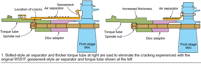
If you’re unfamiliar with the torque tube, which joins the compressor and turbine sections of the rotor, and the air separator, look at the sketches in Fig 1. Note that cracks have occurred only on torque tubes configured for goose-neck type air separators (left-hand drawing); also that the cracks are concealed by the air separator.
Cloyd told the group that the initial flaw size is very small and something you would not look for in a normal inspection. It takes about 30 to 70 starts for a crack to propagate from a tiny corrosion pit to the size required to initiate a vibration event, growing radially outward and circumferentially from the downstream nut-retention relief groove. The crack proceeds slowly after initiation, he continued, then accelerates through a high-cycle fatigue phase to failure. Cloyd recommended that if a vibration event points to a torque-tube crack, confirm with ultrasound before removing the rotor.
He added that thermal transients heat the air separator faster than the torque tube during startup, increasing the stress at the relief groove. Spindle-bolt torque and gooseneck air-separator compression variations, in combination with a high delta in stiffness near the U-notch, are considered likely contributors to crack formation. The preload on all spindle bolts must be uniform during rotor assembly, Cloyd stressed.
Two engines in the fleet are known to have reported forced outages caused by vibration events traced to through-cracks in their torque tubes. A crack was found on one unit after only 10,000 operating hours (but 90,000 hours on turning gear); it continued for about 45 deg around the circumference of the torque tube and vibration became a concern.
Owners facing a torque-tube issue have several options, according to Cloyd: Replace the rotor (exchange with a new or refurbished rotor), in-kind torque-tube replacement, and an upgrade option. The last includes a replacement torque tube with additional thickness where cracks have occurred and a bolted separator (elimination of the spring-loaded goose-neck design).
Cloyd is bullish on the last option because MHPS has nearly 3-million actual operating hours and 30,000 starts on its bolted separator (right-hand sketch in Fig 1) without a failure. MHI redesigned the torque tube and air separator for engines of its manufacture after a failure about 20 years ago at a plant equipped with the industry’s first 501Fs (a joint project with Westinghouse).
The first MHPS torque tube/bolted separator was retrofitted on a W501F in start/stop service more than a year ago and has not experienced any issues. Another retrofit is planned for fall 2019; eight more projects are in the pipeline. Cloyd recommends replacing the torque tubes and air separators on all W501 rotors that come into its shop.
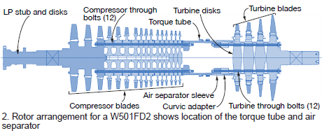
A pre-CRI inspection is recommended at any outage with a cover lift. This includes visual inspections, hardness testing, and a phased-array UT inspection of the spindle bolts to detect the presence of a crack, if one exists, prior to pulling the rotor and entering a CRI inspection. What you’ll see when you look under the hood of a W501FD2 is shown in Fig 2.
Owner/operators benefit from having the best data possible in advance to be sure the work scope addresses all the issues of concern and the necessary parts are available when work on the rotor begins. Keep in mind that historian data are important to the accuracy of any rotor assessment. Trending of rotor ageing characteristics improve component life predictions.
A compressor-disc creep and corrosion assessment should be conducted during the turbine inspection (TI) in advance of the CRI. Turbine- and compressor-blade groove wear and corrosion evaluations are recommended as well. There should be no adverse impact on the outage schedule for this work, which is all done onsite.
Users might consider adding to their onsite inspection scope, the cleaning and NDE of all exposed rotor surfaces. The more information, the better.
A CRI in MHPS’s rotor facility takes about a month. When complete the rotor will be certified for 100,000 hours or 12 years of operation, whichever comes first. While this work is ongoing, performance and reliability upgrades can be implemented. These can add to the scheduled shop time, especially when the required planning is not done in advance.
Of course, unplanned schedule impact can be taken out of the equation with a rotor exchange. The replacement rotor would be installed while the one removed is sent to the shop for refurbishment.
Turbine airfoils. Design Section Manager Travis Pigon reviewed with attendees the excellent service histories of the company’s turbine vanes and blades. Cloyd and his associates have been bringing hot parts to 501F meeting for years so attendees could see and feel first-hand how well they age in service. You can’t get better proof than that. Here, however, the only viable alternative is photos.
MHPS said its parts had not suffered any product issues—such as cracking and coating spallation—because the company had fully addressed failure mechanisms reported in the 501F fleet. Looking at a vane segment removed from a baseload machine for inspection after 40,000 service hours and 290 starts (Fig 3), note that the thermal barrier coating (TBC) is intact, there are no detectable cracks, and no oxidation-caused wall thinning. Same result for the vane segment removed from a cycling machine with 1000 starts (15,000 service hours).
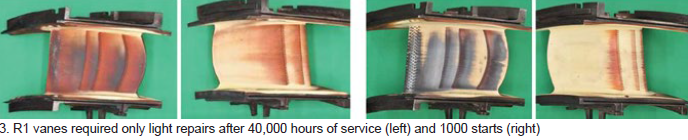
A “light” repair scope was all that was required to prep these airfoils for a return to service. The company’s fallout rate for its R1 vanes over the last four years was reported as zero. Such positive results were said to validate MHPS’s claim of 32k/1200 start intervals.
Inspection results on first-stage blades were the same, except for visible cooling traces on the airfoils (Fig 4). Fallout rate attributed to design issues was 0%, 13% from FOD, tip rubbing, etc.
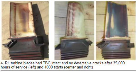
Repair scope was light, like that for the R1 vanes.
Results from inspections of second-stage vanes and blades were similar to those recorded for R1 airfoils, except for minor platform cracking on some vanes. No matter, light repair scope with 0% fallout validated inspection intervals of 32k hours/1200 starts.
Photos shared of MHPS hot parts in W501FD2 engines after more than 23,000 operating hours and 700 starts revealed sufficient margin to operate longer intervals.
Matt Marinelli, GT design engineer, presented on MHPS exhaust solutions to address recurring durability issues associated with the legacy W501F exhaust cylinder (such as cracking in the diffuser, dead-air-space strut shield, aft static seal, and struts) and manifold (diffuser and Y-joint cracking).
Marinelli discussed improvements made by MHPS to the original W501F exhaust cylinder—including improved material, floating diffuser system, cooled robust aft static seal, and passive strut cooling system. Improvements to the original W501F exhaust manifold: more durable material, reduced upstream flange thickness, partitioned teardrop, vertically bolted two-piece design, and elimination of circumferential ribs.
Next, he identified some of the technical solutions available to extend the operability of customer exhaust systems until replacement is possible.
MHPS’s retrofit offering is based on the company’s M501F3 and G-frame designs, said to have had no history of fatigue cracking in millions of hours of operation. It is a drop-in replacement with no auxiliary-piping or foundation changes necessary. A design feature of particular interest to owner/operators is the ability to remove the exhaust bearing through the teardrop rather than removing the tail cone or the upper half of the exhaust cylinder.
Siemens
Given the challenging business conditions facing power generators and their equipment/services suppliers, Siemens opened its two-hour session at the 2019 501F Users Group meeting with a brief discussion of some steps it is taking to support customers during these turbulent times.
The company said it is investing more on the service side, including the upgrade of repair facilities in Winston. Siemens is in the process of moving its Houston repair business to Winston because there’s not enough business to sustain the Texas operation. The transition is expected to take about a year. Regarding staff, some new-unit employees are transferring to openings in the service group to both maintain a critical mass of talent and to cope with the falloff in sales of new units.
The Siemens session included updates on gas-turbine technology and the company’s field-service operation, as well as an overview of mods and upgrades for increasing output and improving performance (interval extension, advanced DLN and ULN, FD6 thermal performance upgrade, low-load turndown), and a review of the company’s expanded-scope solutions (exhaust-gas attemperator, exhaust purge credit, value-added controls).
Focus here is on key points made during the technical update. Registered users can access information communicated during the Siemens program by reading through the presentations on the user group’s website or by visiting the OEM’s Customer Extranet Portal (CEP).
Siemens’ Customer Conference for F, G, and H users
Another venue for sharing experiences with owner/operators of Siemens 501F gas turbines is the OEM’s customer conference. It is held about half a year after the 501F Users Group conference and vendor fair. In 2020, the 501F Users Group will meet at the Hilton in West Palm Beach, February 9-13; the Siemens Customer Conference for F, G, and H Technology will be at the Renaissance Orlando at SeaWorld, the week of June 15.
The 2019 Siemens meeting at the Hilton Orlando Bonnet Creek, June 17-20, attracted nearly 200 F, G, and H owner operators from around the world. Vinod Philip, CEO, Service Power Generation, opened the meeting by sharing the Gas and Power spin-off status and how creating a unique energy and power company will bring attractive opportunities. The focus for this conference was to discuss technical issues, findings, resolutions, and recommendations for the F, G, and H frames.
It included various frame-specific technical presentations by the OEM’s experts, closed customer sessions, feedback sessions, breakout sessions on steam turbines, generators, and digitalization, networking opportunities, and a Technology and Innovation Showcase which included participation by 20 preferred suppliers invited by Siemens.
There were many opportunities to visit the Showcase during the event where users had the opportunity to see hardware, tools, and technologies and discuss topics one-on-one with subject-matter experts. Three-dozen Siemens booths featured gas-turbine components, digitalization, generator and steam-turbine innovations, plant operations support and training, grid solutions, virtual reality, mods and upgrades, field-service technologies, robotic inspection, environmental health and safety, and much more.
Users who missed this conference can access the presentations on Siemens’ Customer Extranet Portal.
The technology presentation began with an overview of the torque-tube cracking issue that the steering committee requested be included in presentations by the four OEMs participating in the meeting.
MHPS and Siemens, the manufacturers of record for torque tubes supplied with 501F engines, had the most experience to share on this subject. The former said torque tubes of its design had not cracked in service. Siemens reported investigating three cases and was told of two more which it had not evaluated at the time of the meeting. The affected engines had the following operating histories: 9589 equivalent baseload hours/1410 equivalent starts, 13,541 EBH/646 ES, and 133,161 EBH/5655 ES.
Common findings included these:
-
- A review of manufacturing and repair records did not reveal any findings with a connection to the mode of cracking.
- Materials evaluations indicated no anomalies in chemical composition, mechanical properties, or metallographic structure.
- Fractures initiated on the ID of the first undercut near the aft turbine bolt flange.
- Corrosion present on the initial crack surface suggested slow propagation of the defect.
- Crack initiation was consistent with low-cycle fatigue which transitioned later to high-cycle fatigue from rotational bending, as indicated by rapid crack propagation and an increase in vibration. In one instance the unit tripped on high vibration.
- Siemens has not determined the cause of crack initiation; however, a leading theory is a combination of spindle-nut tensioning sequence and a pit exposed to corrosion over time.
The last four bullet points are in general agreement with findings by MHPS as noted in the preceding section.
Siemens’ recommended actions for its torque tubes are similar to those offered by MHPS in the preceding section:
-
- UT the torque tube after removing the air separator, and after restacking the rotor, to confirm the absence of cracking.
- Replace the torque tube during a shop visit for rotor and casing inspection and evaluation (RCIE)—if warranted based on consideration of accumulated and projected actual starts.
- Polish and paint rotor fillets after disassembly to prevent corrosion and pitting.
Siemens reported that it has updated its guidelines for bolt tensioning/sequence to reduce the probability of torque-tube cracking. Plus, it is considering torque-tube design mods for the fleet’s advanced Fs. No such action is being taken on the earlier 501F engines at this time.
Radial rubbing at the interface of the air separator and torque-tube seal housing was described. One significant event fleet-wide was reported; however, five rotors were replaced based on inspection findings. About 100 engines were inspected. Refer to service bulletin SB3-15-0046-GT-EN-01 for details and recommendations.
The rub mechanism described relates to the manufacturing process and certain transient conditions that reduce the clearance between the air separator and torque tube—likely in combination.
Inlet manifold cracking has been reported on some FD3 engines with welded-pipe struts, which were installed to provide axial stiffness. Cracks typically are found in the pipe struts and welds, between the strut and manifold. A switch to bolted pipe struts was identified as a viable solution.
Cracks in the compressor inlet manifolds of 17 F5 engines (30 units inspected) were reported as having been identified. Noise-suppression blankets consisting of an acoustic cover sewn to a thermal insulation layer coated with fiberglass cloth can mitigate cracking. A dozen engines outfitted with the blankets prior to first fire have been inspected to date without evidence of cracking.
Four-way joint leaks continue to be a nuisance. Leaks are generally found at vertical flanges on both the upper and lower halves of the compressor, combustor, and turbine casings near the horizontal joint. Leaking has been attributed to casing distortion, thermal stress, cracks, irregular surfaces, and foreign material between mating joint surfaces.
Leakage mitigation/prevention involves proper bolting, high-temperature sealants, and solutions that divert gas away from the leakage path. Regarding bolting, success has been achieved, the group was told, by alternating the tightening sequence between the vertical and horizontal joints while working away from the four-way joint.
The harmonized exhaust for the F5ee model, and the variable-guide-vane distress observed on the inner diameter of some F5 and F5ee units (Stages 2 and 3), received air time as well. However, given the association of these issues with only the fleet’s most advanced engines, most CCJ readers would have only passing interest. Those wanting to know more are referred to the presentation posted on the 501F Users Group website.

