


Planned and emergent field replacements and repairs are top of mind for most every O/O with a sizable GT fleet. A representative from a Florida utility covered experience during a major FA.03 to .04 upgrade outage in 2024 at an 1100-MW 4×1 CC in commercial operation since 2003-2004. The title of the preso, “Two Fields Down, Two to…Oh!,” hints at what’s in store for readers.
The rep began by stating that “these fields [Hitachi generators] were never pulled” over their two decades of operation and “we could have been better at borescope inspections” over that period, even though vibration levels were never exceeded or caused a trip (robotic inspections were done). Each of the attached GTs had around 3000 starts.
Because shorted turns were detected ahead of the planned shutdown, the fields were pulled as part of this outage to evaluate suitability for service. Pre-outage, one unit showed a clear correlation between bearing vibration and field current after specialists evaluated flux probe readings, field current, and VAR test data. One other unit also revealed moderate indications from flux probe readings, while the other two showed only minor indications. Check out the slides for detailed graphs and field evaluation of data.
To avoid prolonging the outage, specialists elected to exchange fields on the two more troubled units. Other inspections, which resulted in the other two fields having to be replaced, are reviewed pictorially in the slides,
That experience translates into the first big lesson learned: Conduct BIs during minors to evaluate end turns. The second big lesson learned: Transmission planners may require fresh analysis to ensure the NERC MOD-026 and MOD-027 model constants are the same.
Generator core damage discovered after a BI minor was reviewed by a southwest US O/O rep. You’ll want to check out the pictorial to see how 70% of stator iron could be damaged, with no deviations in output or temperature prior to the shutdown, nor any evidence from the PI historian.
Needless to say, a 5-7 day BI turned into a 35-day outage, after a contractor inspecting the field body first noticed dents and scratches along the surface, then found severe damage to the core and field body. Metal objects were observed on the core iron and stuck in between the vent ducts. Later, 11 metal pieces were found inside the core. The collector end was intact, as revealed by damage maps (see slides).
Apparently, what happened was a pair of channel locks left by a millwright during a Fall 2021 outage found its way into the core, even though no core repair work had taken place. This is articulated as a foreign material exclusion (FME) process failure. A millwright has to be inside the core to guide the field back in, and the channel locks either fell out of a pocket or were placed on top of the field and not reclaimed. Corrective actions taken to avoid future FME failures are listed.
Balance of slides review the repair plan, prep, iron core grinding, shop field inspection and rewind, and post-repair tests. Question, perhaps rhetorical, asked at the end: “Did operators hear anything bouncing around in there during their walk-arounds?
In-place machining of collector radial leads was tackled by an O/O in Texas, slides essentially providing a pictorial of inspection, testing, and replacement of both inboard and outboard leads and associated hardware. Although a prior visual inspection showed no obvious signs of overheating, tracking or distress, the outage plan included replacement, along with H2 seals, which had been responsible for an increase in forced outages within the fleet.
Troubleshooting a generator line-side failure could have been named, according to the Italian O/O rep who delivered the talk, “how troubleshooting can be complicated if you don’t have enough information.”
- Summary of the salient lessons learned include:
- Make sure 100% of the generator is protected against ground faults
- Verify routine relay protection systems
- Inspect grounding systems as part of routine maintenance
- Make sure disturbance registers work properly
- Check the integrity of resistors located on top of the generator neutral connections
- Spares are key to prompt return to operations.
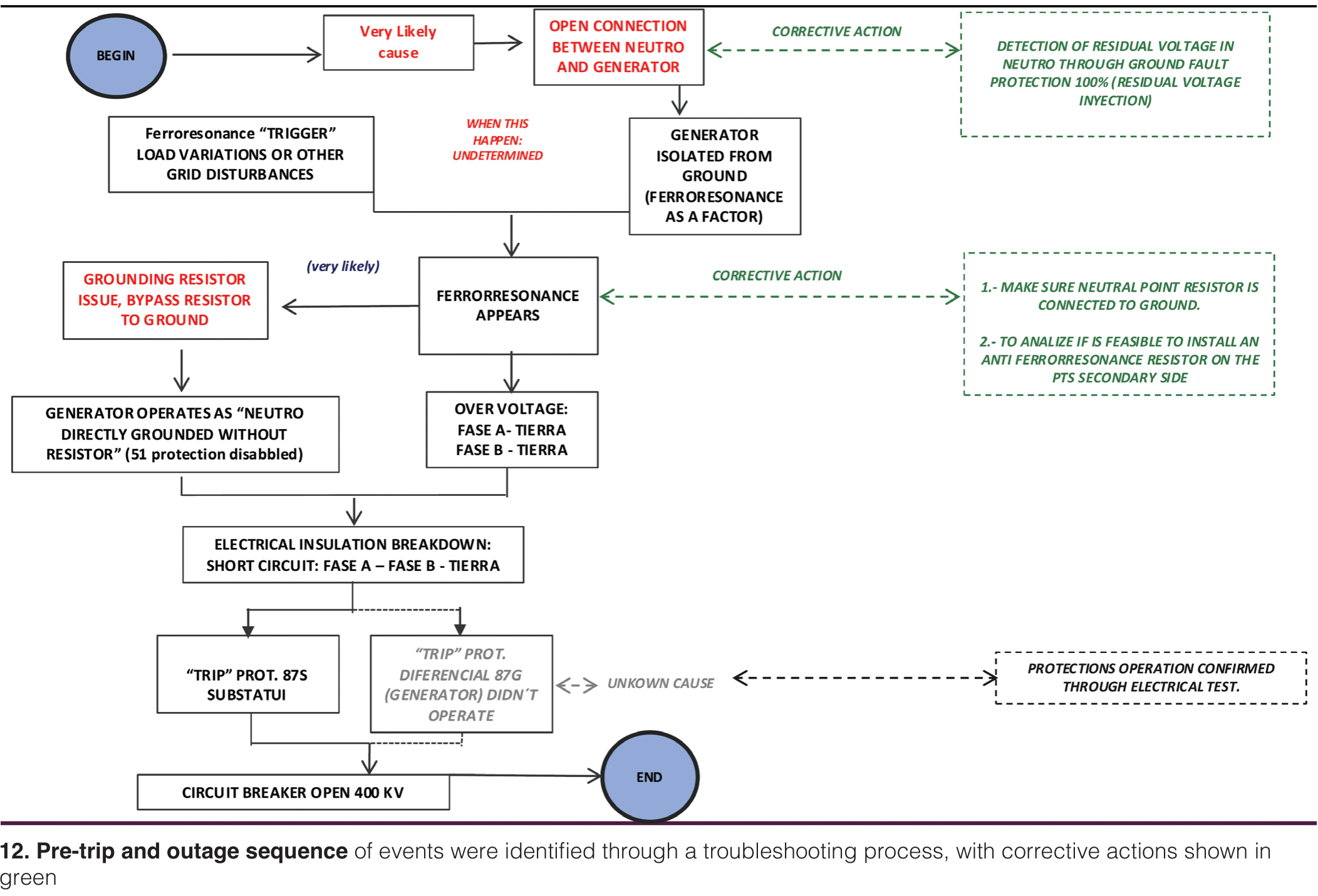
The sequence of events (Fig 12) which led to the ST/G trip and subsequent 12-day outage; the associated inspections, troubleshooting logic, findings, and thought processes; and the recovery plan and repair process are all explained in great detail, with very helpful diagrams, in the slides.
A bowed stator core in a model 7A6A 100-kVA air-cooled generator (frequently cycled) was the topic of a presentation by a western US utility. Big concern here was whether the same issues would be found with two other similar units. Evidence leading to a thorough investigation were increasing annual partial discharge readings over the years, high voltage testing in 2021 (very low PI values and significant DC leakage above 22 kV), and subsequent visual inspection, all of which suggested core sagging at the turbine end with a peak deflection of 78 mils.
Other findings include: Knife test indicated adequate core tightness, some support plugs were installed behind the core, and ElCid tests revealed no problems with the core.
Engineers decided to perform a core loop test, verify tightness of several through-bolts, and evaluate prior operating data, specifically vibration and stator temperature. One bolt broke away at 1535 lbs force, but the other three were tight. All other through-bolts were checked and found tight. There were no significant temperature changes; random high vibrations on the generator forward end could not be correlated.
Since no broken welds of key bars to the web wings were noticed, plant decided to do a stator rewind, with additional flat fillers (with side ripple springs) at the turbine end of the stator, with semi-annual partial discharge (PD) monitoring. First four months of operation showed no abnormal vibrations and normal stator temperatures.
Critical questions: (1) Were the support keys underneath the core engineered properly, (2) why were issues not addressed in previous OEM reports, (3) was core restacking required on this machine, and (4) will the same issues affect two other units on-site of the same vintage and manufacturing location?
Generator inspection troubleshooting is a high-level overview of tips and traps by an O/O responsible for hundreds of machines. Some bullet points and reminders:
- Electrical testing only indicates an issue exists; visual inspection will identify the issue and location.
- Finding an issue “right before” failure is exceptionally rare
- Photograph everything during an inspection and include an object for scale when possible.
- Balance of slides are photos with examples of the types of indications likely to be found.
Generator rotor main lead failure. Subtitled “magnet madness,” a rep from one of the largest O/Os in America discussed a recent failure of a permanent magnet generator (PMG) exciter, discovered after a steam turbine trip on both bearing No. 6 and exciter bearing high vibration. Operators reported “smoke on turbine deck coming from the PMG.”
Incidentally this failure occurred only five months before the conference, proving the willingness of many users to share as soon as possible on events which could affect the entire community. I mean, you really can’t say enough about the dedication of these guys and gals.
The exciter was disassembled, with signs of rubbing on the stator and magnet assembly, so the PMG was sent to a motor shop for testing and repair. Then the 0-pole covers were removed, isolating the generator rotor from the exciter. A “hole” was found on the 180-deg pole at a damaged radial lead. The OEM had no replacement leads available and recommended that the rotor be removed and sent to their shop, but there was no shop space right away.
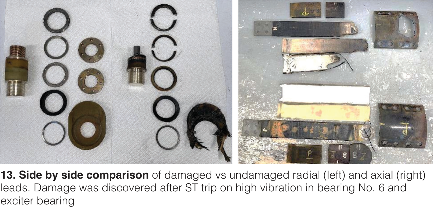
The balance of the slides review how the plant came up with a “workaround repair” for the damaged radial and axial leads (Fig 13) on site to return the unit to service as safely and quickly as possible, while waiting for the OEM’s replacement parts. Though these are seemingly small components, the repair and recovery was not straightforward, as you’ll see in some of the close-up photos.
Meanwhile, the exciter was disassembled and tested, with acceptable results, and the PMG stator cleaned and tested, also satisfactory. However the magnets suffered impact damage from the vibration trip. Thus began the “magnet madness.” The vendor could not source magnets in a timely way and the PMG was shipped back to site to attempt repair. Finally, a magnet supplier was found who would test the magnet and supply new ones – in 13 weeks. Plant found a temporary AVR (automatic voltage regulator) to supply power to the exciter.
The PMG was later reassembled, with balance weights added to compensate for mass lost during grinding, then pressure tested with the new radial lead. This still isn’t the end of the story for which you’ll have to check out the slides. Fortunately, it has a happy ending.
Retaining ring pitting, rotor inspection and repairs, TIL 2256 (rotor slot liners and top U channels), and TIL2370 (head insulation and G10 liners) were addressed by a representative from a Texas plant. A team of third-party services reps were involved in the work. Summary of the work (slide deck has photos and details):
Generator rotor was removed and shipped to the shop for rings-off inspection and testing.
Excessive pitting was found at contact points within the dampening fingers and shrink fit area. Decision was taken to replace the two retaining rings.
Top U-channel insulation was replaced due to cracking in the top corners (TIL2256)
Rotor wind, head insulation, and titanium liners were replaced with new insulation and G10 liners from the OEM (TIL2370).
Damper rings and fingers were found in poor condition (most of the silver plating was missing), removed, and sent to a local vendor for refurbishing
Rotor was reassembled as shipped to another facility for high-speed balance and overspeed tests.
Rotor returned to site, reassembled, started up, and taken to speed with no issues.
Failure of a rewound generator after six months was reviewed by an O/O rep from a Texas facility. This 500-MVA H2 and water-cooled unit is no spring chicken, entering commercial service in 1977. It experienced a major forced outage a year later, 2000 starts by mid-1994, a rewound rotor in 1998 (main shaft lead “burnt in two”), and another rewind in 2009 following low megger readings.
The investigations and troubleshooting began in mid- to late 2023 when changes to on-line insulation resistance were observed, with the first generator-ground alarm in early May. With consistent alarms present and other evidence, the plant prepared to disassemble, troubleshoot, and repair during a fall outage.
In the shop, heavy oil contamination was revealed, along with retaining-ring line cracks, a slot liner patch (from the 2009 rewind), improperly applied turn insulation, and coil cracking. A rewind was performed with its own set of challenges, but the peaking unit was able to run numerous times throughout the following summer (2024). Late in September, the unit tripped on vibration after the insulation resistance monitor alarmed. Unit was again disassembled for troubleshooting the next day and, after site testing, was sent to the shop.
Shorted turns were revealed from RSO [??] tests after the turbine-end retaining ring was removed, along with damage to coils 5&6 on the turbine end, braze joint fracture on bottom of coil 5 (vendor only did NDE on every other brazed joint), and burned-through retaining ring insulation from a fault.
Options at this point included a partial rewind of damaged coils, or obtain a spare rotor from a recently retired sister unit in Louisiana. Plant purchased the spare rotor and returned the unit to service while the original underwent more repairs. Much concern existed around the integrity of all the brazed joints. High current testing and thermography were inconclusive.
Ultimately, the decision was made to rewind the machine with all new joints. Because the first attempt at high-speed balancing identified shorts, blower hubs and retaining rings were again removed and sources located. Final balancing was successful.
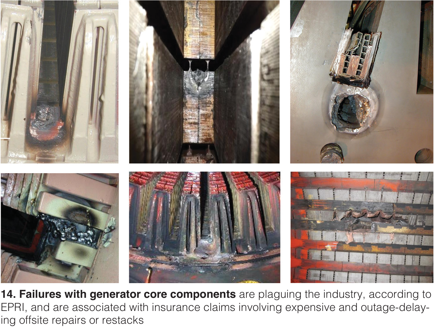
Too many core issues (Fig 14) are affecting our industry, according to an EPRI presentation, and they are “ugly and expensive.” Largest contributors to core failures are lamination, insulation, and deterioration, but stator winding short circuits, oversaturation, and poor repair/rewinding workmanship are significant as well, according to some insurance company data presented.
Balance of slides review data from EPRI studies, evidence from visual inspection, knife checks for core tightness, core-bolt torque check, stator core and ELCID testing, step iron testing, core loop high energy test, hot spot infrared thermography, on-line condition monitoring, acoustic monitoring, and leakage flux.
GUG vendor presentations
Following are a few highlights from GE Vernova presentations based on CCJ notes taken during the sessions (slides available through the GEV customer portal).
7A6 Generators: Fleet Performance, Operation, and improvement. The 7A6 generator fleet is second only to the 7FH2 in size. The speaker (in jest, presumably) called the generator the “revenue center” and the turbine the “cost center.” Common fleet issues include:
- Corona bar damage at the end of the bar (older units)
- End winding dusting and greasing (which can be “locked up” with wicking epoxy)
- Stator wedges relaxing with time, which vibrate in their slots and cause higher end winding vibration.
A patented process for shimming stator wedges in place has been developed with a major US O/O. It was first performed in 2016; six years later, 151 out of 156 wedges were “still tight.” It is described as a “semi-permanent solution.” The process should be considered when between 25-80% of the core wedges are loose or when there’s more than 4 ft of loose wedges.
Unearthing Root Causes and Top Technical Insights (RCAs/TILs/ERs) Impacting the Fleet. Although it’s been almost a year since the conference, this round-robin review of the most recent TILs shouldn’t be ignored.
TIL2545 (issued January 23, 2025) recommends replacing fan blades in H53(324) generators with the latest blade configuration at the next scheduled outage for “select units between 2018 and 2021.” This is to accommodate the update in the number and size of radial cooling holes in the stator core.
TIL2119-R1 describes a pole-to-pole connector replacement without pulling out the rotor and removing retaining rings. Affected H2- and air-cooled units typically have 700+ starts and were built after 1996. No alarms/trips occur prior to findings and no forced outages are associated with this upgrade. Root cause is listed as low-cycle fatigue (LCF) during start/stop cycles (primary) and insufficient wetting of the brazing surface (secondary). This solution replaces one which employs a U-shaped connector to move stress away from the brazed area, but does requires rotor removal.
TIL2519 (July 18, 2024) addresses tilt-pad bearing damage and involves replacing existing upper two pads with a narrower pad configuration and applies to generators equipped with four-pad tilted bearings commissioned between 2015 and 2018. A65 units “will see this issue,” but while it is described as a relatively painless change if you are doing other work on the unit, it does require removal of the bearing assembly upper half. Caution: These are not inventory parts; lead times are described as 40+ weeks.
TIL2241-R1 (July 18, 2024) recommends inspecting rotor winding connections for broken lamellas, since there are no forced outages attributed to this issue, or alarms/trips prior to discovery. However, recent unit inspections reveal 4-9 lamellas with indications (out of 10-11 for each end winding). Root causes are listed as LCF and HCF (low- and high-cycle fatigue) and reduced flexibility and stress concentration from the presence of brazed material. Solution is to replace with an upgraded connector.
Topics which surfaced during a roundtable on the GVPI generator fleet included:
- Circuit breakers/disconnects and grounding switches between the generator and GSU (generator starting unit) are experiencing ground faults
- The “Fast Wedge Retightening” system has now been conducted on 12 units (a robot is used to tighten wedges with rotor in place) but no subsequent checks for tightness have occurred yet.
- OEM is in the “early stages of applying AI tools
- An interesting application of 3-D printing is to print a component using a “cheap material” to validate dimensional accuracy before the actual component is made
- Torsional vibration monitoring will be included in the OEM’s Gen Advisor package
- Aeropac (and TEWAC) main leads are failing and leading to forced outages – three units suffered this event in the first half of 2025.
“Generator Field and Stator Testing – Good and Bad Results, and Making the Bad Good, Again,”
Jamie Clark, AGT Services
This comprehensive primer on all things inspection and testing begins with some words of wisdom: Employ only experienced generator specialists, the dirt tells a story (don’t clean it up before the specialist has completed the inspection), speed does not equal quality and will not save you money, and extending inspection intervals is proving detrimental to generator reliability. New units are built with less margin, less mass/MW, and lower cost materials.
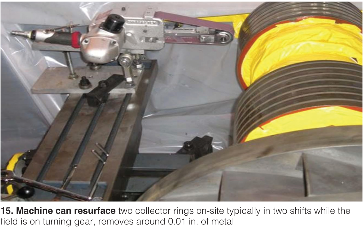
Balance of slides reviews most every type of visual, mechanical, and electrical test and inspection procedures for all the important components of a large generator, replete with photos showing typical findings and in some cases solutions (Fig 15). Don’t be put off by the number of slides (100+).
“Generator Field Failures,”
Global Energy Services Alliance
You’ll likely need to contact the presenters for the details as the slide deck is mostly photos illustrating causes and sources of common failures such as retaining rings, turn insulation migration, ground insulation, turn breaks, coil distortion, thermal sensitivity, radial lead connections, and bearings.
“CPV Valley and Cutsforth: Enhance Technological Advancement with EMI Monitoring Diagnostics,”
Cutsforth
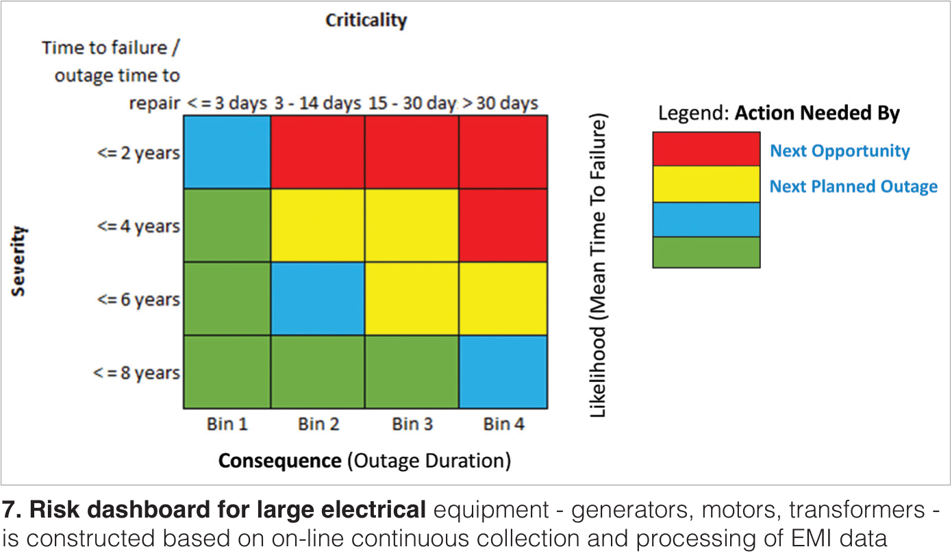
Monitoring electromagnetic interference (EMI) to detect incipient failures in large generators was first proposed in 1979 according to Cutsforth specialists. Over the following four decades, several large utilities progressively applied the concept to monitor generators, motors, transformers, and other large electrical components. Now, a plant in upstate New York is working with Cutsforth to convert ~50 plant-wide EMI detection system outputs into 20 diagnostic severity and urgency indicators and a color-coded production-risk dashboard of potential consequences (e.g., outage duration) paired with a list of troubleshooting steps to inform the outage scope.
“Event Analysis,”
Douglas Weisz, Hubble/Beckwith Electric Co Inc
Not for the faint of heart, most every slide in this 150+ deck is dense and packed with data, equations, graphs, etc., for analyzing the following events: Phase differential current, Isync trip, neutral overvoltage, inadvertent energizing, volts/Hz over-excitation, GSU trip, phase distance, third harmonic neutral under-voltage, ground differential current, reverse power, negative sequence over-current, and loss of field.
“Generator Acoustic and Vibration Testing and Analysis,”
John Mihalic, EME
Presenter states that loose cores have been identified on over 50% of machines tested acoustically over the past five years, noting that they often are not tested unless there is evidence of an issue. Acoustic testing is a non-invasive method to analyze generator vibration; identify issues, especially stator core looseness; and plan proactive preventative maintenance. Instruments and setup, procedures, fundamental theory, data analysis, and examples (including abnormal conditions) are explained.
“Thermal Sensitive Generator Rotors: Testing, Causes, and Repairs,”
Roger Kondos, Entrust Solutions Group/TG Advisors
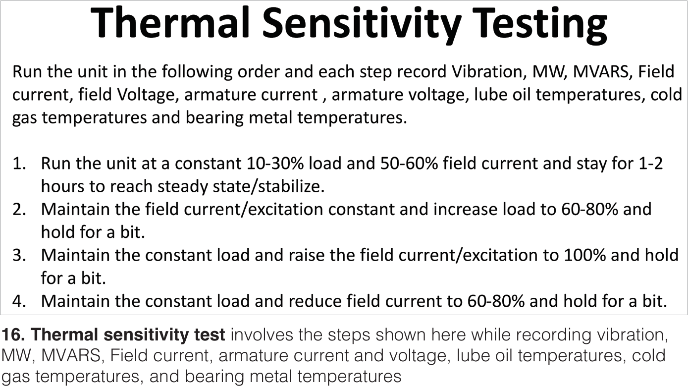
A generator field is deemed “thermally sensitive” when there is a bow in the rotor that changes due to excitation.” Reversible causes include shorted turns, distance block fitting, blocked ventilation, and heat sensitive rotor forging; Irreversible causes are wedge tightness and insulation. Slides offer a testing procedure (Fig 5) and mitigation (essentially limiting load/MVARs output) and repair options. Data, analysis and conclusions from a case study are included.
“Generator Stator Troubleshooting,”
Howard Moudy, National Electric Coil
After formally defining troubleshooting, a disciplined and systematic approach to problem solving, and it’s purpose, including collecting and analyzing data and identifying and prioritizing contributors to the problem, slides present three case studies with different generator models–suspicion of moisture contamination, T6 neutral ring failure, and ground fault T2-T5. A few of the case study key points worth noting:
- Access to a high-voltage laboratory can be critical to success
- Sometimes commercial priorities take precedence over best technical practice, such as a repair process that costs half of what a rewind would.
- Sometimes a recommended test is not practical from the user’s perspective
“Thermal Testing Generator Rotors,”
Keith Collins, MD&A
Slides review aspects of operational speed testing, such as overspeed or at-speed proof test, balance, running IR (insulation resistance while spinning), flux probe (for shorted turn detection), thermal test (or heat run) for vibration stability at speed, and explores thermal sensitivity and potential causes. Case studies before and after repair data round out the deck.
“Novel Findings in Synchronous Machine Modeling,”
Wayne Cassidy and Dan Leonard, Peregrine Engineering Consulting
Who wouldn’t want to view a slide deck that begins “When are power plant people popular at cocktail parties? After the blackout.” This presentation is really for the folks who deal with the grid after the powerplants deliver their electricity. Essentially it reviews, compares, and contrasts three simulation models for round-rotor machines – GENROU, GENTPJ, and GENQEC – with the intention of establishing that GENROU be clearly allowed in future round-rotor model database submittals to grid authorities.
“Generator Uprate Risk Assessment,”
Jacques Leger, E-M/WEG Group
Typical main design constraint for a generator undergoing an uprate beyond its nameplate rating is stator winding temperature and rotor winding temperature. Other factors which must be assessed are airflow, bearing load/temperature, shaft stress/fatigue life, foundation loading, retaining ring material, and excitation to the field — all reviewed here in detail. A case study for a 2-pole generator uprate and voltage change is presented. CCJ