


Lessons learned from a steam turbine forced outage is an example of why every owner/operator should have people at these conferences. The HP/IP incident in question involves two and an half rows of rotating blades liberated at the platform, four rows of stationary blading missing 10-60% of airfoils, rubs observed on the lower halves of the HP seals and packing, and a total of 15 rows of rotating and stationary blading needing to be replaced (Fig 8).
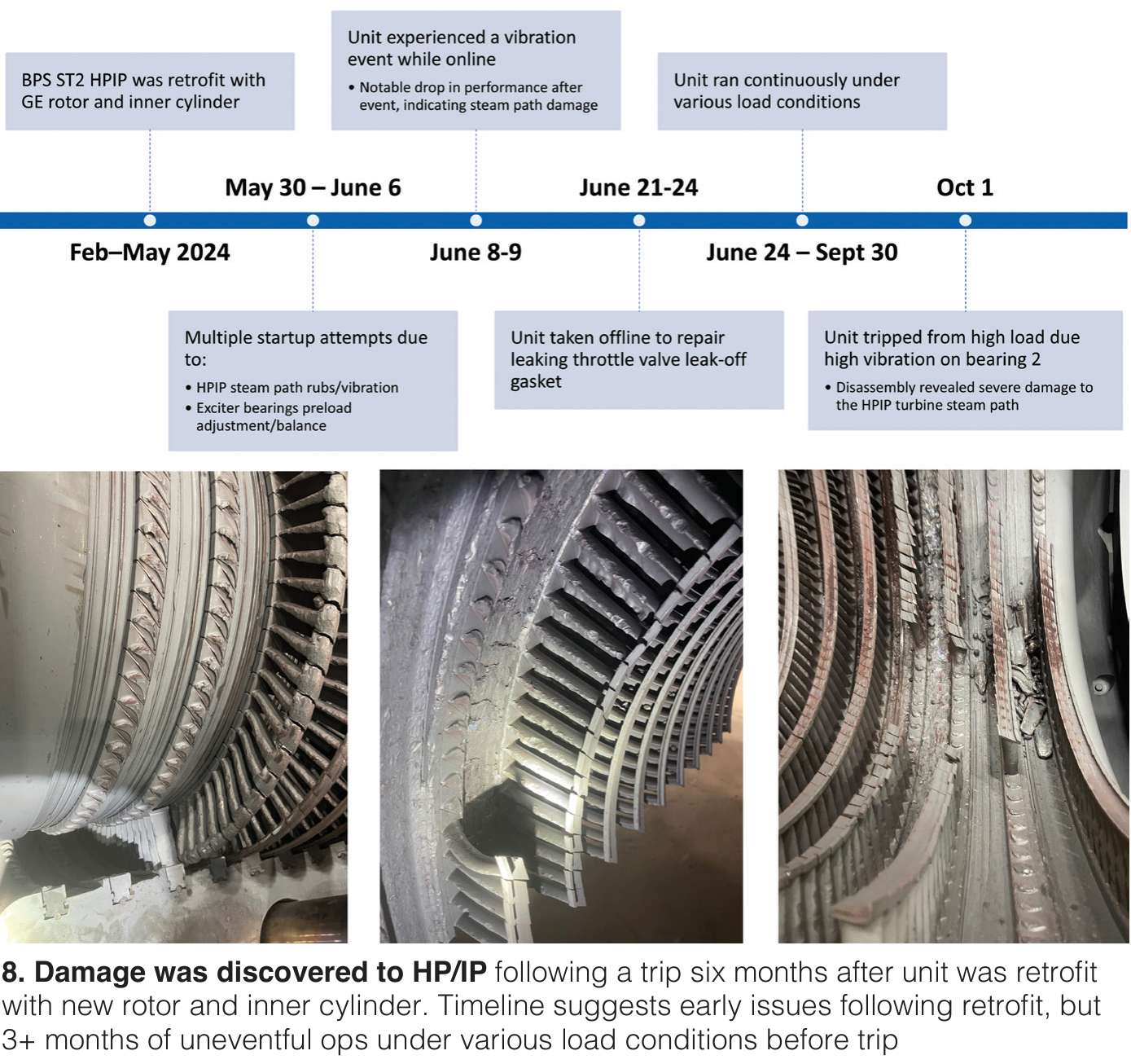
The OEM root cause analysis (RCA) is a real mouthful but goes like this: Cold misalignment led to hard rubs during startup which generated excessive heating of the shrouds, leading to loss of pre-twist in the blades because they were more susceptible to the high cycle fatigue by which the blades were liberated. Addressed as part of the remediation plan are the misalignment, seals and clearances, LVDT position errors, insulation, steam blows, and oil flush. Reams of operating data ahead of the failure are also included.
Worth noting is that this ST unit was commissioned in 1957, then repowered with the conversion of the old fossil plant to a 4×1 CC in 2003. More recently, when concerns with rotor bow (run-out), creep/embrittlement, and inner casing cracking surfaced, a new HP/IP rotor and inner cylinder were installed in early 2024. While the failure occurred October 1 of that year, several operating hiccups were noted prior, supported with much operating data ahead of the failure.
In a stellar example of collaboration, four utilities got together to develop a scope strategy for a D11 high-pressure/intermediate pressure (HP/IP) ST replacement. Among them, the utilities operate 18 D11 units. Slides review common end-of-life issues such as outer shell thermal stress, creep, deformation, cracking, and leakage; rotor bowing, creep strain in dovetails, and LCF at wheel fillet; and diaphragm dishing. Each utility had different motivations for the replacements.
The lessons learned slides should be invaluable to any users contemplating such a replacement. Replacements for these collaborators are scheduled progressively between fall of 2027 and fall of 2030.
Creep life management in steam turbine casings was the subject of the kickoff presentation by an EPRI specialist. “Time-dependent (creep) damage is an emerging concern in casings across the thermal fleet,” he said. Unfortunately, the onset of creep damage (cavities) is “impossible to detect.” He aimed to “debunk some of the earlier assessments and “creep-fatigue claims” and decouple creep from fatigue. Both can be observed simultaneously.
Current casing materials are not meeting performance expectations, he said. Essential question: “Can you explain how your casing got to its current condition?” Put another way, are damage mechanisms in your casing being confirmed or assumed? For example, creep damage detected in the casing may be localized given its sensitivity to temperature and stress.
EPRI has fitness-for-service material data sheets supported by two decades of analytical data (data OEMs and service providers do not have) and an active investigation program for D11 casings and repair techniques and strategies. The slides offer some of this data and a few case studies.
A few points which could make you nervous about your aging casing, such as 15% increase in stress can lead to a 2x change in life, a 25 degF higher temperature will decrease casing life by a factor of 2, sub-surface creep damage may exist despite an undamaged surface, there’s no benefit from post-weld heat treatment on creep performance in casings, and it is impossible to rely on NDE alone for condition monitoring.
The specialist also focused on filler metals for repairs. Matching filler metal strength to the repair material is not a trivial exercise. Higher strength filler material can actually accelerate damage evolution, especially in degraded or damaged material which was not removed during the excavation process.
While some of the slides require a background in metallurgy, the overall message is that you should have metallurgists guiding your decisions on aging casings, not just OEMs and service providers.
Last stage blade droplet erosion was addressed by a second EPRI specialist. Part-load operating conditions increase relative droplet velocity by up to 40% and increase erosion rates by a factor of 16. Exhaust hood sprays are of particular concern.
Damage measurements, usually taken manually, are often very subjective, he argued, and it is difficult to develop generalized predictions from specific sets of turbine data, although it can work better under steady state operation. During the Q&A, one user noted a special concern with erosion at the Z-lock attachment.
From the commercial end, OEMs typically do not recommend weld repair; they’d rather sell new blades, and many users prefer the conservative option even if replacement is premature. Repair service firms don’t share their repair techniques or experiences so it’s difficult to discern repair efficacy.
EPRI is pressing hand-held 3-D scanners into service for more accurately assessing droplet erosion damage on trailing edges, blade tips, Z-lock shrouds, and other parts. Goals are to aggregate the data into “erosion maps” that could lead to advanced evaluation of erosion rates in specific areas.
As with the talk on casings, the slides are numerous, dense, and busy, suitable for a day-long workshop. They cover damage mechanisms and influencing factors, damage characteristics and measurements, consequences of droplet erosion damage, erosion damage prediction and assessment, and blade restoration techniques.
It’s important to note that weld-repair techniques for last-stage steam turbine blades date back to the early 1980s in coal- and nuclear plant steam turbines, so there’s a wealth of knowledge and experience to tap into if you’re interested in avoiding wholesale blade replacements.
ST rotor crack repair. Speaking of weld repair, ST experts from one of the nation’s largest O/Os reported on a rotor crack repair applying the guidelines in EPRI’s “State-of-the-Art Weld Repair Technology for Rotating Components, Vol 1: Weld Repair of Steam Turbine Discs and Rotors.” The LP ST (part of a 1990-vintage peaking CC unit limited to 10% capacity factor because of environmental restrictions) is described in the slides as an “unusual configuration” requiring “unorthodox lifting.”
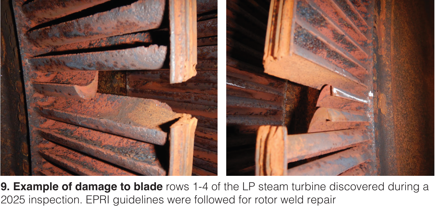
During a 2017 inspection to locate the source of air in-leakage, specialists found heavy deposits on rows 1-4. Plant continued to operate (low annual hours) until a vibration trip event in January last year. Upon inspection, significant damage to stages 1-4 was discovered (Fig 9). The blades were replaced. Balance of the slides offer a detailed pictorial with diagrams of rotor repair, including prep, machining, welding, post-weld heat treatment and finishing; blade replacement, high speed balancing at a facility in Houston; and reassembly.
ST/G alignment challenges. A third EPRI presentation stressed that the time required for ST/G alignment measurements and corrections are often under-estimated. Alignment issues are 3-D in nature with an almost infinite number of possible options for addressing them, and great difficulty arriving at their root causes. For example, bearing vibrations caused by misalignment are often addressed through field balancing adjustments during startup, but this may conceal the root cause.
Slides review alignment main activities, preparation and planning (review of operating data, gathering records, tooling and special equipment, etc), lessons learned and best practices, etc. Another interesting caution: Using advanced tools for measurements do not necessarily resolve alignment issues.
Stop valve control valve (SV/CV) lessons learned, presented by a representative of a large O/O and an MD&A specialist, begins with troubleshooting issues arising during daily valve tests, leading specialists to suspect the integrity of the CV springs. Subsequent outage activities include cleaning scale off the valve discs and balance chambers, and replacing the valve springs, which exhibited a free length 1/2 in shorter than in the “new” state.” After this work, the valve passed the test. A modification of the balance port may also be conducted in the near future.
Also discovered (and depicted in photos) were solid particle erosion of the valve seats and valve stems and thermal fatigue cracking of the valve body. General takeaway: When daily valve testing is not successful, remove the valve from service.
In diaphragm crack discovery and repair, an O/O specialist teamed up with a Sulzer specialist to review stage 23 diaphragm issues and repair from a 2002-vintage 120-MW A10 ST which had changed operating profile in recent years from baseload to peaking.
Initial discovery and NDE results are captured in a few slides, then mitigation options assessed. Shop inspection revealed linear indications from 1/16 to 3 1/2 in. at the welds between the vanes and inner/outer webs, linear indications in the stationary airfoils, cracks in the leveling blocks, and heavy damage to the anti-rotation slot in the lower half of the diaphragm. Oddly, the vanes are hollow. No previous cracking of vanes had occurred.
The repair process, accepted as temporary to extend component life, included reverse engineering and design modifications to reduce thermal gradients during starts, stops, and load changes.
Failure, mods, and material analysis of L-0 ST blading (Siemens design, 10 m2 and 6.9 m2 length) traces need for accelerated precautionary inspections of these blades to a blade root liberation event in 2005. Perhaps of most interest to users is that the utility presenter developed its own PAUT (ultrasonic) inspection protocol and applied it to two units every 200 starts from 2006-2013 with no indications found. Other slides focus on findings and analysis in 2013 of the unit which experienced the 2005 event.
The OEM supplied the utility with new sets of redesigned L-0 blades, together with new guidance to increase allowable starts between inspections to 400 starts (side exhaust) and 500 starts (axial exhaust). Assuming the guidance would be conservative, the utility conducted material testing of the new blades to determine if inspection intervals could be modified. Crack growth rates between the new and old material (X5 and X10) were projected to be similar, so inspection intervals should be similar, too. However, time to crack initiation of X5 was greatly improved. Goal is to optimally manage crack initiation and growth, given high starts on these units, and long lead times on spares if indications are found.
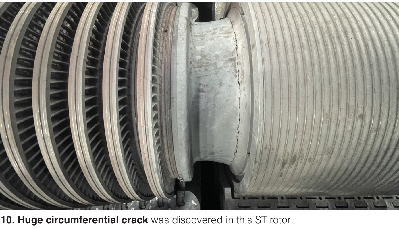
The good, bad, and ugly. You may be unsure of where the “good” is in this slide deck but if you have “wreck on the road” viewing fantasies, this deck features a huge circumferential crack (Fig 10) in an undesignated ST rotor, last stage blade erosion near the platform, missing, liberated, and deformed LP blades, and blades which look like gravel went through them along with the steam. If you have a new green ST engineer on your staff, this might be the slide deck which “puts the fear of god” in him.
Remaining life assessments, presented by Entrust Solutions, offers a generalized roadmap, focused on the areas of highest risk (blades and rotors), and broken into phase 1, an asset review, and a phase 2 comprising detailed engineering analysis. Results are prioritized, given scores and ranked, and fed into a multi-year capex plan. Some specific points: not all failure modes are linear, changes in duty cycle and site operational and maintenance practices must be factored in, and more detailed outage diagnostic techniques may be needed as the unit ages.
Entrust has conducted over 500 ST/G life assessments, with a higher level of requests from insurers in recent years. Data attributed to EPRI and FM Global shows that the highest risks stem from flow-path components, specifically blade/dovetail cracking.
A case study from one plant-wide assessment summarizes risk-based condition of plant components using available inspection data and walk-down info. Table showing unplanned maintenance risks by component, issue, timing, probability of occurrence, and recommendations may be especially revealing.
STUG vendor presentations
“Can the Steam Turbine Support Daily Cycling?”
Steve Radke and Thorsten Wold, Siemens Energy
Answer to the question is yes, if your unit includes a “world class stress controller” managing predicted load margin and optimizing GT ramp rate, and a “high-powered static frequency converter” for fast acceleration. According to the OEM reps, up to 85 MW/min ramp rates are possible in an automated start-up sequence. The full “flex plant design” can achieve a hot start in 20 min.
“CC Performance Testing and Steam Path Audit Case Study,”
Jim Miller, MD&A
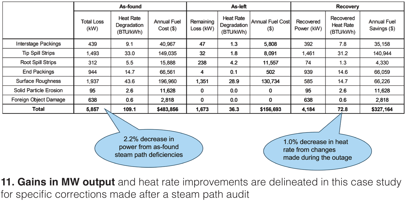
Improving turbine cycle heat rate not only leads to significant annual cost savings but informed decisions for prioritizing maintenance. As a rule of thumb, a 1% step change in turbine efficiency at valves wide open should cause an investigation. Two primary aspects of a performance improvement program are (1) conduct as accurate an efficiency test as possible before and after the audit, benchmarked to a reliable reference, and (2) inspect the steam path off-line to identify deficiencies and quantify economic impact.
Examples of typical as-found sources of performance loss include seal leakage, solid particle erosion, deposits, foreign object damage, water erosion, changes in blade trailing edge thickness, surface roughness, and flow changes from HP turbine inlet area alterations. Other common issues which surface are damage to first reheat stage, inlet seal ring leakage, and distortion in packing casings and diaphragms. Results from a case study round out the slides, with a breakdown by issue of performance impact and economic benefit/cost ratios (Fig 11).
“Oil-Your Hidden Asset!,”
Eddie Rowland, C.C.Jensen, Inc
“When do you need to change your oil?” the presenter asks, but not before urging his listeners to treat oil as an asset, not just as a consumable replaced on a fixed schedule. While go/no-go answers for the question “don’t exist,” presenter offers some good guidelines based on common tests, such as viscosity, total acid number, additive depletion, particle count, ASTM E2412, MPC membrane, ultra-centrifuge, water/moisture, foam, demulsibility, RULER, and RPVOT. Maintain it, monitor it, clean it, and extend its life, presenter concludes.
“Untapped Efficiency: Steam Turbine Packing Rings and Seals,”
STAR, a PowerParts Group Company
Presentation reviews why packing seals exist in an ST; how they affect efficiency and economics, especially for baseload machines; issues which arise over time, such as axial rubs, distorted diaphragms affecting seal clearances, diaphragm dishing/creep, axial tilting, and others. Last set of slides explain advantages of company’s “sensitized” packing over conventional designs.
“D-11 Retrofit and Valve Upgrades,”
David Hicks and Kevin Roy, MD&A
First part of the deck describes the characteristics of the D11R (D11 retrofit) product and the fleet problems it addresses. Characteristics recounted include a double shell (full inner casing and cooling cell on upper outer shell); HP/IP rotor with higher rotor stiffness, excellent stability and vibration characteristics, higher creep and fatigue strength, and designed for modern CC cyclic duty; stationary vanes (reaction design) which avoid dishing and enhance efficiency; and higher efficiency steam path.
Second part of deck lists valve upgrades which address oxide formation and stem binding, erosion, low cycle fatigue (LCF) cracking, integral seat restoration, and hot swap assemblies.
“Repeated Challenges for Steam Turbine Outages,”
Tim Midgette and others, Viking Turbine Services
Outage issues discussed at length, along with case study examples and illustrations, are D11/A10 shell tap studs (e.g., thread relieving), LP inner casing horizontal joint erosion and bolt hole damage/repair, A10 N3G3 packing casing distortion (accelerated dishing with weaker materials), N2 packing fit cracks (unplanned repairs), D11 HP/IP horizontal joint blue checks, atmospheric-relief-diaphragm (ARD) assembly issues, main steam valve issues and repair planning (main stop/control valve and reheat valves), and D11 creep. There’s significant verbiage on these slides so think of it as more of a guidebook in slide deck form.