The HRSG Forum isn’t just another industry conference—it’s the only “user group” event where every session is open to all participants, fostering real-time exchange across users, OEMs, consultants, and solution providers. No sessions are restricted but are moderated by Bob Anderson (Competitive Power Resources) and Barry Dooley (Structural Integrity, UK) to ensure fruitful presentation and discussion outcomes. The 2024 HRSG Forum delivered critical technical insights on catalyst management, boiler feed pump reliability, flexible operation challenges, advanced metallurgy, and pressure part failures. With demand rising, resources tightening, and equipment aging, this report is packed with practical takeaways and cutting-edge updates to help you stay ahead. If you’re in the business of making HRSGs safer, cleaner, and more reliable, you won’t want to miss the 2025 HRSG Forum, July 21–25 in The Woodlands, TX. The following report is divided into four parts:
- Catalyst system O&M workshop
- Boiler feed pump O&M workshop
- HRSG Forum general session
- EPRI: HRSG/HEP technology transfer
Following the first day of training on catalyst systems and boiler feed pumps, conference sessions began on Tuesday with opening remarks by Anderson, who introduced co-chair Dooley and the steering committee of Scott Wambeke (Xcel Energy), Albert Olszewski (Constellation), Yogesh Patel (TECO Energy), and Eugene Eagle (EPRI).
The 300 attendees represented end users/operators, HRSG manufacturers, service providers, specialized consultants, and a wide range of equipment designers and fabricators.
Anderson stressed the following: “At this year’s event, unique to North America, you will find a balanced combination of presentations that provide practical information, question and answer sessions, and facilitated spontaneous discussions on issues of interest. You will learn more about HRSGs, how to maintain and operate them better, how to improve their design and performance, and you will share your own expertise and experiences with others.”
This was only the second in-person event since the impact of Covid-19. Noting the alignment with HRSG forums in Europe and Australia, Anderson announced that 12 countries were represented this year in St. Louis, and more than half the participants were attending in person for the first time.
The HRSG Forum requires no membership or credentials, just an interest in learning more about HRSGs and their operation. Selected presentation highlights for days two and three follow.
The demand for power
A recurring topic in presentations and discussions was the growing demand for power, both in the US and throughout the world.
Peter Van Allen, project manager at Arizona Power Service Company (APS), offered a concrete example of owner/operator programs to keep the power flowing. His agenda topic: HRSG considerations and analysis before GT upgrade.
He began by highlighting the massive electricity demand growth in Maricopa County, AZ, driven largely by the booming computer industry. “One new operating data center is the same energy load requirement as operating 300 Walmarts,” he explained. Maricopa County has seen some of the highest annual population gains in the US since 2016, and coal plants in his state will be retired by 2031.
Along with this growth, he stated, “extreme weather has become the norm. In 2023, Phoenix experienced 55 days above 100F.” He reminded participants that existing combustion turbines can derate on extremely hot days.
“Therefore, current and long-term electric reliability is paramount,” he continued. “We have 8000 MW of new resources in the near-term action plan and more than twice that over the 15-year planning horizon. Natural gas is a critical part of this energy program.”
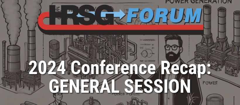
Case history West Phoenix CC5 thermal performance upgrade project, recently back on line.
The objective: 55 MW capacity increase for the 5A and 5B combustion turbines (Fig GS1). Scope included HRSG and other balance-of-plant improvements to support these CT upgrades.
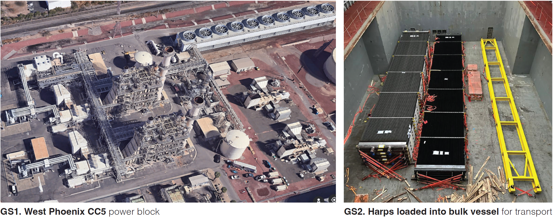
Greg Rueff, Vogt Power International, joined to discuss the HRSG work details. Work packages included:
- Heat transfer components – 28 harps (Fig GS2).
- Harp structural supports.
- Cold reheat piping and flow elements.
- Gas baffles.
- Steam drum separators.
- Duct work casing, liners and insulation.
- HRSG piping.
- Attemperators (resized).
- Valves (safety, control, IP)
- Drain pots.
Project benefits included:
- Final 58 MW increase.
- Increased mass flow to HRSGs.
- Turbine NOx reduction from 20 to 10 ppm (reduced ammonia consumption).
- HRSG backpressure reduced by 6 in. WC (largely by blast cleaning).
Presenters ended with the topic “How to rerate a boiler” and had a strong suggestion for owner/operators facing such a project challenge: “The Authorized Inspector is an important part of the team,” they stressed.
Questions/discussions reviewed installation details, new component design life, and carryover testing frequency.
Mega trends
Tom Freeman, GE Vernova, also highlighted increasing demand as he discussed “Mega Trends” in what he called “The great awakening: Make my plant run to 2065.”
In an interesting industry overview, Freemen walked through the four primary mega trends of load growth rate, asset age, decarbonization, and grid emergencies. He explained that we are now in a third gas turbine industry bubble (the last was 1999 to 2005).
Quoting Scientific American and others, he continued: “The dawning Artificial Intelligence boom could use a shocking amount of electricity.”
He then offered the example of Buying a Ford F-150. Each Google search can use 0.3 watt-hours of electricity, he explained, such as a search for: “What is the appeal of a Ford F-150 truck?”
Using ChatGPT4 for “What about Ford F-150 trucks for post midlife individuals living in the suburbs?” uses 3 watt-hours. Creating an image (ChatGPT4) of a person contemplating buying a F-150 truck consumes 10 watt-hours.
His message: More computer thinking means more energy consumed. We can’t build power generation fast enough, and interconnect (grid) issues for PJM and ERCOT are staggering.”
More cycling
Prewarming system options for startup was presented by Joe Schroeder, J.E. Schroeder Consulting.
A cooperative team of Bob Anderson (Competitive Power Resources), Schroeder, Norm Gagnon (Arnold Group), Eugene Eagle (ex-Duke Energy), and Bill Carson (EPRI) has been studying methods of reducing temperature and pressure issues of system startup using warming systems.
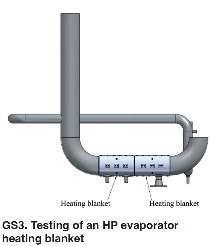
He began with a turbine heating blanket overview.
He then added downcomer heating blankets stating that “electrical heating offers several advantages over steam sparging” and discussed a specific field trial at Duke Energy (Fig GS3).
Eugene Eagle, EPRI, joined to review testing and results.
Selected summary details:
- The test proved that downcomer heating blankets can maintain drum pressures and keep the unit in a warm standby condition.
- Heater installation was quick and simple.
- Adding heat to HP, IP and LP evaporators may be better than adding to HP alone.
- The tested unit had less severe tube differentials and no large quenches or tube temperature down shocks during startup compared to the unheated twin unit.
One summary point: control panels were installed as a temporary system, operated locally at the HRSG. This demonstrated that the concept would work, and calculations for heating requirements were accurate.
A large, permanent power supply for these warming systems will be required. Analysis is ongoing and a final report is pending.
Questions/discussions included project duration (5 days), use of thermocouples, heater design life (20 years), stack temperature profile, and impact on relief valves.
Thermal transients and chemistry
Barry Dooley provided global updates on both thermal transients and system chemistry, noting that failure mechanisms keep happening although they are clearly understood.
He offered his list of repeat cycle chemistry situations that he has closely monitored since 2008. Stressing the commonality, he noted that these situations and damage details are based on operations, not on a particular HRSG OEM.
Chemistry impact on HRSGs can fall into some general categories:
- Chemistry-influenced tube damage and failure mechanisms.
- Corrosion product transport.
- Steam turbine deposits/damage/failures.
He then focused on single-and two-phase flow accelerated corrosion in combined cycle/HRSG plants, and ended with a detailed list of Technical Guidance Documents available at no charge through The International Association for the Properties of Water and Steam (IAPWS).
During discussions, Bob Anderson, who works with Dooley on these surveys, added an interesting comment: “Tube-to-header failures are generally caused by thermal events, not by manufacturing errors. Metallurgical analysis of the failure site is critical for finding the failure mechanism needed to determine the root cause.”
Hydrostatic testing
Ian Perrin, Triaxis Power Consulting, focused on Hydrostatic testing: what, why, and when? This topic was first discussed at the most recent EPRI Boiler Reliability Interest Group (BRIG) meeting in December 2023.
Hydrostatic testing (aka hydrotest) is system pressurization with water (an incompressible fluid) to test for workmanship, leaks, strength and system integrity. It is governed by ASME Section 1, PG-99, and is traditionally part of the commissioning process. The standard is 1.5 times the maximum allowable working pressure (MAWP) of a system.
An important note: Post-commissioning at less than 1.5 times MAWP is a pressure test, not a hydrostatic test. The terms are often mis-applied. Normally, pressure testing is below 1.5 MAWP and is often below operating or working pressure.
Perrin then cautioned that there are numerous “myths” about hydrostatic testing, which he labeled “Nonsense you can read online.”
One example: “The Claim: Pressure or hydrostatic testing will allow for determination of remaining useful service life, or continued safe service life.” This is a myth, suggested Perrin. “Hydrostatic testing or pressure testing tell you absolutely nothing about remaining useful service life, fitness for service, or continued safe service life,” he stated. He added that “very large cracks can pass hydrostatic testing but may propagate in service (due to fatigue or creep).” Thermal-stress-driven failures will not be addressed or detected.
Most HRSG damage issues are from thermal events, and locations of high thermal stress may not coincide with locations of high stress due to pressure.
Perrin offered past examples of catastrophic failures that have occurred during 1.5X hydrostatic testing.
Post-commissioning, your authorized inspector (AI) may require a 1.5X hydrostatic test, but this is not recommended, he concluded.
A lot of interesting discussion followed including use of flaw grooves for testing (ID and OD), ultrasonics in lieu of hydro, magnetite fracturing, chemical cleaning, 1.5 hydro on low pressure boilers, lack of industry standards on pressure testing schedules, acoustic listening devices, and jurisdictional rules and inspector approvals.
Inspection and maintenance
Jeff Henry, Applied Thermal Coatings, offered The value of metallurgical analysis of failures, or how to extract the necessary information from an analysis to support plant operation. Access more detail on the topic from Henry’s HRSG Forum 2023 welding workshop.
Proper metallurgical analysis is “an important component of any root cause investigation,” he stressed, “and is necessary to prevent repeat failures.”
Done properly it provides information regarding both primary and secondary damage mechanisms. It explains the damage within the context of equipment operation so that the root cause analysis can focus on information relevant to the failure sequence, avoiding unproductive diversions into non-relevant issues.
“The failure analysis is not the root cause analysis,” he explained. “It is a critical component of the RCA.”
Going deeper: “It is not just the academic background of the analyst that is important – if, at some basic level, the analyst does not understand how the equipment was designed, how the component was manufactured and how the system in which the component was installed was intended to operate, then it is unlikely that the results of the analysis will be of any real benefit to the plant in preventing future failures.”
Discussions included the value of knowing the sample location, and improper assumptions of oxygen as a cause for failure.
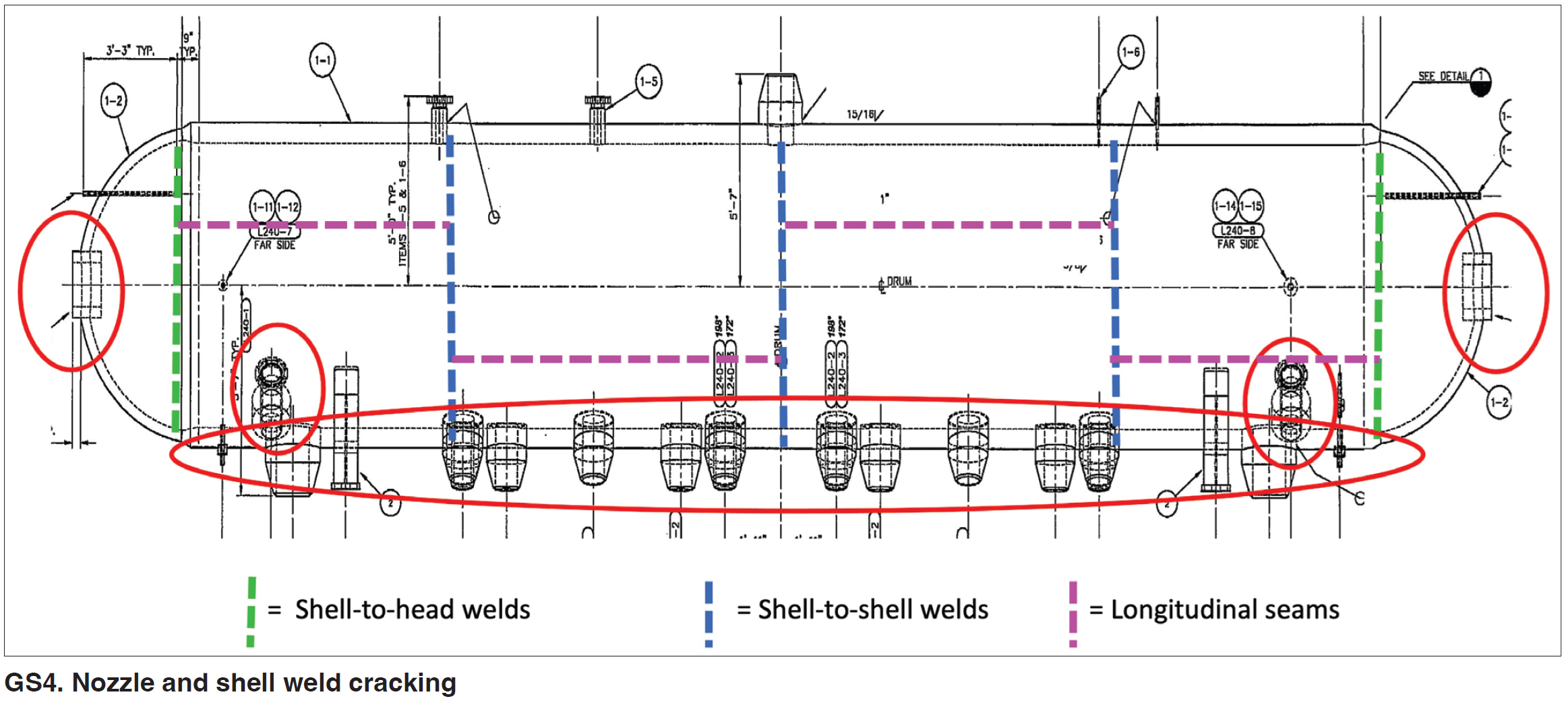
Steam drums. Lester Stanley, HRST, then offered Drum weld inspection experience and lessons learned.
Stanley raised two key points (among others):
- On-off cycling creates stress in thick pressure parts due to the thermal transients within the components (e.g. HP steam drums).
- Searching for drum weld cracks often results in stress on the people involved, expensive repairs, and missed planned outage dates.
He first focused on steam drum locations to inspect (Fig GS4) for nozzle and shell weld cracking, outlining the principal areas where stresses occur: downcomers, risers, manway rings, and shell-to-head welds, among others.
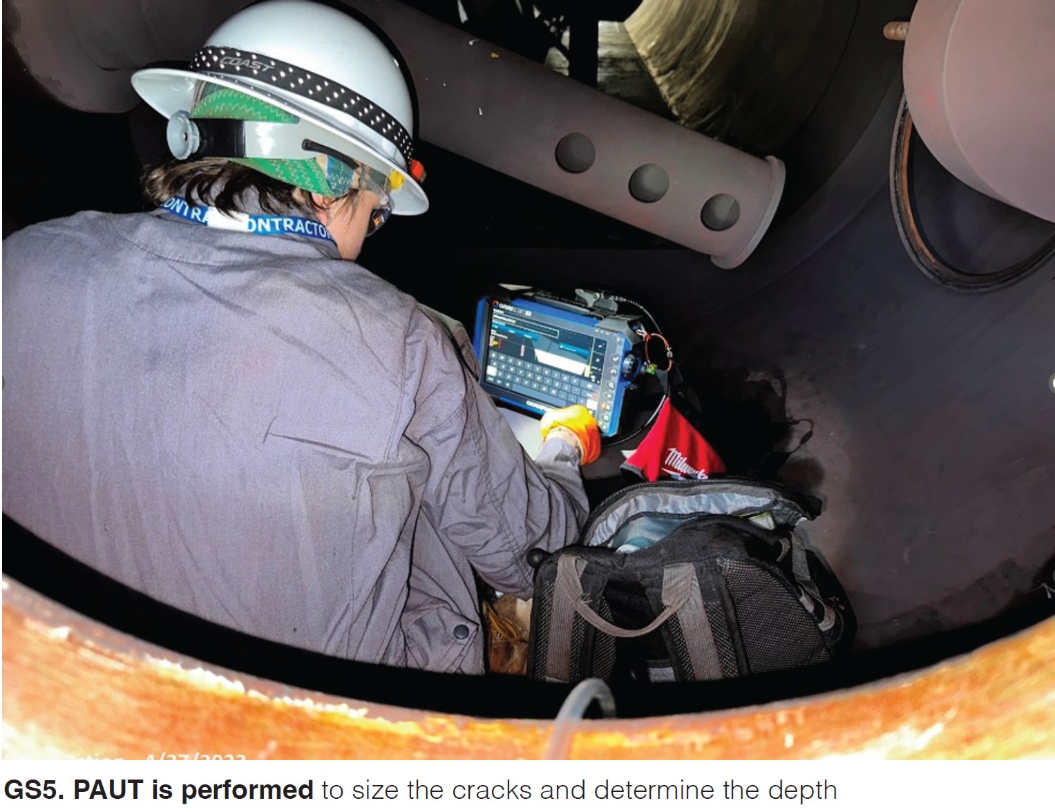
He then walked through some visual and phased array ultrasonic testing inspections (Fig GS5), critical crack size assessments, monitor/repair decisions, and a variety of lessons learned.
Stanley’s summary:
- Perform thorough HP drum weld inspections to catch problems early.
- Complete pre-outage drum shell ASME minimum wall thickness calculations.
- Perform “Critical Crack Size” analysis of the larger HP drum welds.
- Plan ahead for drum internals surface preparation actions.
- Develop a precise drum weld inspection map to keep track of findings.
- Utilize critical crack size graphs to make fast decisions on “repair or monitor” if weld cracks are found.
- Carefully document the location, size and depth of cracks, especially if the cracks are adjacent to other cracks, due to interaction concerns.
Questions/discussions included weld prep cleaning, quantitative predictions, inspections above and below the water line, inside vs. outside inspections, informing the jurisdictions, weld repair experiences, chemistry monitoring, and knowing the geometry.
Stellite. Richard Laukam, Valv Technologies, presented Avoiding Stellite® delamination in high temperature steam valves.
Laukam gave an informative overview:
- Much work by EPRI and others has been put into researching the phenomena of delamination of hard-faced weld overlay (HFOL) Stellite in valves for steam.
- Separation into layers has been observed in valve components at the Stellite/steel interface and in the weld dilution zone formed between the steel and clad.
- Ultimately, disbanding/liberation/delamination of the weld hardfacing from the valve body occurs, resulting in collateral damage to components in the plant.
This topic would be continued by EPRI during Day 4 of Forum 2024.
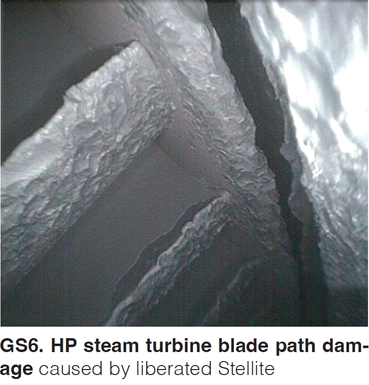
Common delamination areas are high-pressure stop and unit isolation valves and hot reheat isolation valves.
The principal concern is turbine damage caused by foreign objects (Fig GS6). In the worst cases, Stellite pieces find their way to the steam turbine, causing turbine blade and other damage (12,000 to 80,000 hours).
He offered a case study of in-situ repair for reducing delamination. The recommendations:
- Qualify a proper welding procedure.
- Apply a butter pass of Nickel Alloy 625 to the substrate, separating Stellite and F91 material and preventing formation of an undesirable metallurgical condition in the weld zone between the two metals.
- Properly control the heating and cooling during the welding process.
- Thoroughly inspect the freshly welded area with periodic inspections during outages.
And how can delamination be avoided?
He explained that chromium carbide is becoming an option over Stellite. This has the potential to perform better, especially with the coming higher operating temperatures.
He also covered valve seat and disc designs and offered positive results for a 700 MW combined cycle plant operating for 10 years with 2500 cycles.
Discussions included castings vs. forgings, procedures for both, fatigue cracking, and cycling guarantees.
Water treatment. Robert Russell, Veolia Water Technologies, discussed how a Power plant optimizes influent water treatment by changing the coagulant (for improved demineralizer operation).
He outlined the steps involved in influent clarification: coagulation (neutralizing electrical charges), flocculation (bringing destabilized particles together), and sedimentation (settling to the bottom of the clarifier).
His case study was a field application at a northeast US combined cycle plant, highlighting increased filter throughput, direct chemical costs, and related savings including sludge/landfill reduction by 50 percent. Coolers also now run with lower conductivity water, translating to cleaner combustion turbines.
Details included particle destabilization, testing, and the impact of seasonal variations.
Discussions included dissolved vs. suspended solids, reverse osmosis vs. polishing systems, and evaluation of source water conditions.
Steam leakage. Mike McCartney, Shell, offered In-service steam leak mitigation in a petrochemical steam system. Such systems, he explained, often use a common steam source that is distributed throughout many operating units for varied purposes. In a refinery operation, this can include hundreds of miles of piping and associated equipment, and unit operation in one area can impact operating decisions throughout the facility.
He went on to explain the common leak repair methods of crimping and clamping, with direct references to ASME PCC (pressure equipment and piping) Articles.
ASME and owner/operator policies govern the use of crimping and clamping, McCartney explained, and some leaks may be extremely complicated. Both piping size and location matter. Metallurgy is also a critical factor, as is thermal expansion during operation. He offered various application examples.
His base message: safety is paramount, and is “the ultimate decision driver.”
Discussions included similarities of boiler failure mechanisms, condensate issues, and resource limitations on site.
Replacement parts
Viking Vessel Services’ Marshall Hicks and John Null provided an interesting update on the product known as Tuff Tube Transition and related solutions for tube repairs and replacement header installations. The topic: TuffTube update: Regulatory acceptance and header replacements.
The purpose: More than 90 percent of HRSG tube failures occur at the tube-to-header connection, in the heat affected zone (HAZ) of the tube (base metal), at the toe of the weld. See Fig GS7. The Tuff Tube Transition (TTT) product line now includes the Tuff Tube Header Connection (TTHC) shown in Fig GS8.

The product provides a 40 to 60 percent stronger tube-to-header connection in HRSG boilers (based on FEA analysis) and an estimated 50 percent savings in project downtime over conventional installations. US and international patents are pending.
The new Viking Vessel product line also includes the Tuff Tube Purgeless Sleeve (TTPS) shown in Fig GS9 for tube-to-tube connections featuring self-aligned fit-up, elimination of butt welds, and no requirement for radiographic testing.
Hicks and Null also discussed the Tuff Plug for purge-free pipe and tube terminations.
Case study on a recent project, more than 150 tubes were removed to address tube-to-header failures at the center of the tube bundle. Using TTPS eliminated the need for 150 butt welds and radiography, and all welding was completed in 2.5 shifts. Summarizing, “In this emergency repair, the TTT product line allowed the plant to save up to three weeks of down time.”
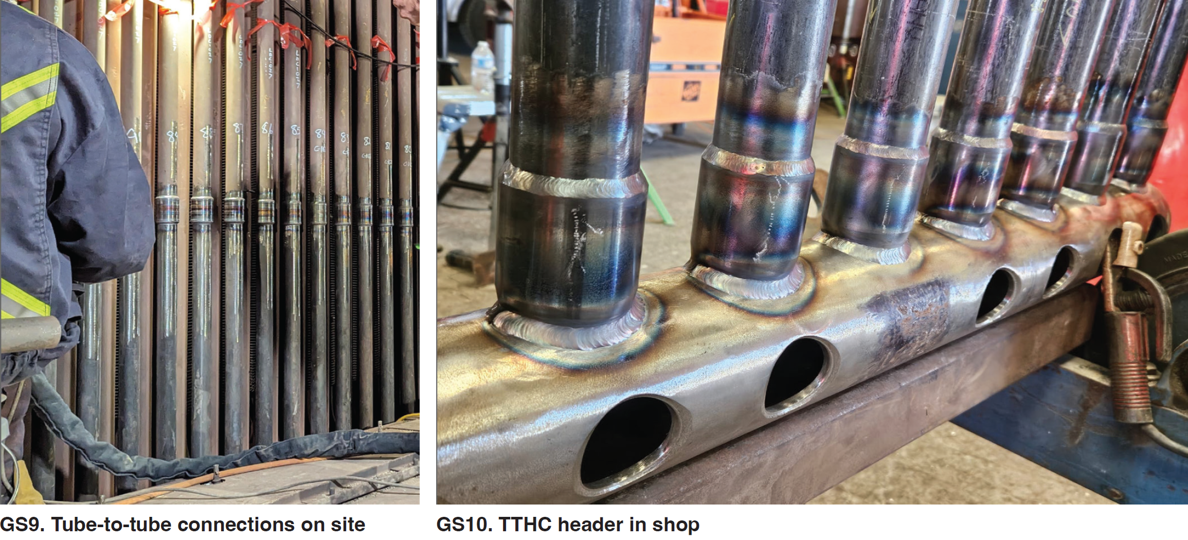
“The TTP HIP (Header Integrity Program) is our engineered solution for replacing old, damaged headers,” they explained. “Most HRSGs in the US are more than 20 years old and have been heavily cycled, far beyond OEM recommendations. TTHC-lined headers can be installed in as little as 10 percent of the time it would take to install a conventional stubbed header.
They offered a case history for three RH1 lower headers, removed and replaced with TTHC-lined headers. The complete removal and install took only four days, providing an estimated 85 to 90 percent savings in downtime for the plant.
These headers (See Fig GS10) were manufactured using the GTAW welding process.
As this is fairly “new” technology, a number of questions and interesting discussions followed including discussions on water-touched versus steam-touched tubes, flow disruptions, tube dimensions and wall thicknesses, condensations issues, and the heat affected zones.
Valves
IMI Critical’s valve doctor Ory Selzer then presented Specifying replacement bypass valves. The fundamental: A turbine bypass is a steam conditioning system that reduces pressure and temperature while bypassing the steam turbine.
In a typical combined cycle plant, this includes valves for:
- High pressure (HP) to cold reheat (CRH).
- Hot reheat (HRH) to condenser.
- Low pressure (LP) to condenser.
- HP to condenser.
Common reasons for replacement are unreliability (noise, vibration, failures), age (materials and lack of maintenance support, particularly P91 from the early 2000s), or a gas-path upgrade (capacity increase over original design). The greatest challenge to pumps is thermal transients.
Selzer discussed design conditions including high pressure drop, sizing and operation, shutoff/actuation, and temperature compensation.
He added: Don’t assume in-kind replacements are appropriate. Any plant changes could require updates.
For replacements, he recommended:
- Use a proven upgrade design with a large installed base; demand reference list with at least five years of operation experience.
- Avoid complex valve internals with an excessive number of parts that can fail; simple trim design is better!
- Make sure you have a serviceable valve with a removable seat (quick change).
He then offered various supporting case studies and stressed the increasing occurrence of “non-OEM parts failures.”
Discussions included inspection frequency, turndown operations, the dangers of forced cooling, fast startups, and operations during lead and lag unit starts.
Cyclic operation. Jeroen Bakker, Advanced Valve Solutions, offered a review of challenges associated with HP bypass valves in cycling power plants.
His overview: In base-load operations, HP bypass valves traditionally served specific functions:
- Open to 80 to 100 percent during steam turbine trip.
- Bypass HP steam during HRSG startup and shut down, performed a few times per year.
“But today,” he said, “these valves face more frequent operation, impacting reliability and system integrity.”
There are two principal types of bypass valves: those with integrated dump and ring-type coolers, and those with perforated plates and steam atomizer (Fig GS11).
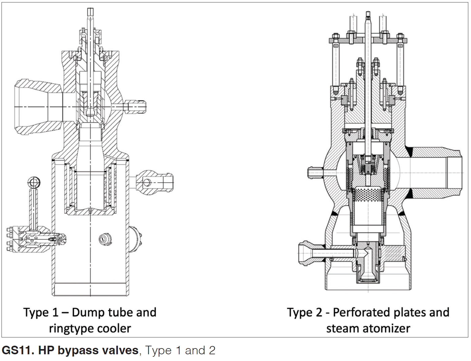
Transitioning from base load to start-stop operation has revealed recurring issues with Type 1 (dump tube) valves:
- Failure of dump tube integrated in the valve body.
- He covered dump tube failure due to water impingement, high frequency vibration at full steam flow and part load.
- Cracking of nozzle at steam line weld (continuous thermal stress regardless of steam flow).
- Thermal stress in downstream piping leading to cracking and deformation (primarily at high steam flows).
He suggested how to prevent dump tube failures (Fig GS12):
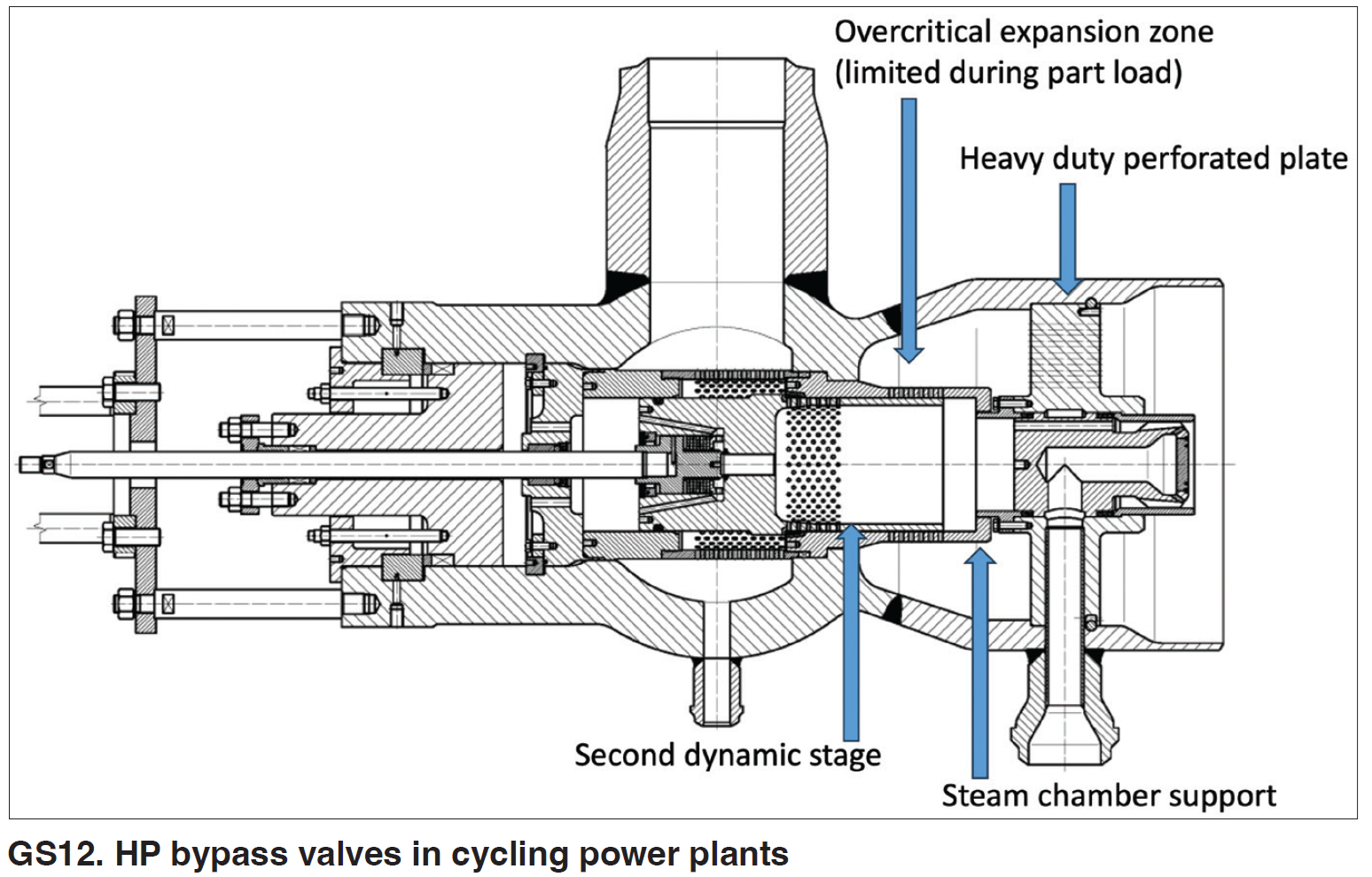
This would support dump tube or steam chamber after first stage at the bottom.
- Introduce a second dynamic pressure stage to prevent overcritical expansion and minimize turbulence (oscillation).
- Eliminate dump tube, replacing it with heavy duty perforated plates.
He then suggested how to reduce thermal stress in the downstream line and nozzle weld:
- Replace perpendicular spring-loaded nozzles by axial spray injection through steam atomizer.
- Insulate spray water supply line by use of an inner liner.
He summarized: “Make it a storm, not a hurricane.”
To paraphrase his overall message, sometimes we need to step out of our comfort zones to revise designs. We can do this with valves, and should do this for other plant components with high thermal stress and turbulence issues.
Discussions included code requirements, drip leg size, interstage drains and sloped piping.
Also, throughout the conference, previously submitted questions were discussed as time allowed. CCJ