
In anticipation of the upcoming 2021 virtual conference of the Generator Users Group, readers may find recaps of user and consultant presentations from the 2020 virtual meeting quite helpful. If you are a registered “Power User,” on-demand recordings and slide decks are available here. GUG2021, which operates under the Power Users umbrella, will be conducted on consecutive Thursdays from July 15 through August 5, plus Wednesday, July 21. Registration for the meeting is limited generator owner/operators (users) and comes with no cost.
User and consultant presentations
Use of an ultrasonic device for locating hydrogen leaks
A handheld ultrasonic instrument commonly used for detecting vacuum and air leaks in powerplants is good for locating leaks of hydrogen and other gases as well, reported an experienced user.
The Fluke ii900 Industrial Acoustic Imager (a/k/a sonic leak detector) relies on an array of 64 digital mics to locate the source of the sound (Fig 1) within a frequency band of 2 to 52 kHz. Practically speaking, the instrument can detect a 0.005-cfm leak at 100 psig from up to 33 ft away. It doubles as a camera capable of capturing stills and video, and has a USB-C port for data transfer.
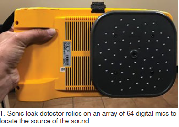
Fig 2 shows the acoustic signal developed by a small hydrogen leak from a generator bushing.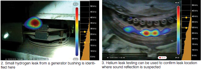
The speaker cautioned that sound can reflect off surrounding surfaces and could be misinterpreted as a leak in the wrong location. If a potential leak source is identified, he recommended viewing the same location from a different angle or distance to verify that the leak source is “true” and not a reflection. Fig 3 is an example of a leak indication caused by sound reflection. The false indication was verified with helium testing.
A thorough understanding of a turbine’s gas piping system and design benefits accuracy. The user added that the default frequency range and filter settings are acceptable for most compressed gas leaks but may require adjustment in noisy environments. This is a trial-and-error “tuning” process.
![]()
User safety—avoidance of slips, trips, and falls—was stressed. Surveyors should remain aware of their surroundings while walking and viewing the screen during scans, attendees were told.
Origins of EMI: History and New Research Users Group
The value of radio frequency (RF) for sensing incipient arcing faults in large generators is well known to electrical engineers serving in powerplants. However, questions remain on how to interpret the RF spectrum signature created by the high-frequency currents flowing in the neutral connection. The speaker said there are many possible sources of RF signals—some are within the generator, some external to the generator.
![]()
In the first group are the following:
-
-
- Partial discharges (corona) within the stator-winding insulation.
- Slot discharges between coil surfaces and the stator iron.
- Sparking from exciters with brushes.
- Arcing between adjacent ends of a broken coil strand.
-
The second group includes the following sources:
-
-
- Corona and partial discharges in the associated high-voltage power system.
- Lightning and switching surges.
- Motors, switches, and other sources in the power station.
-
Application of the RF arc-sensing technique is straightforward. To measure the complete spectrum, simply clamp an RF current transformer around a generator neutral. Radio noise meters covering the frequency range of interest—about 10 kHz to about 32 MHz—provide the measurements in microvolts quasipeak (uVQP). This is explained as sort of a weighted average approaching the true peak value of the frequency component being measured.
Numerous RF measurements from operating machines have resulted in recognizable RF spectrum signatures, generally repeatable and believed to represent the background levels of normally operating machines free of any arcing condition. Note that preliminary measurements suggest that RF noise external to the generator (refer to short list above) is insignificant.
The speaker called for the formation of a new industry group—perhaps something like one of the users groups covered regularly by CCJ ONsite—to research EMI (electromagnetic interference) signature correlation to a given fault condition, develop tools to interpret the signature to fault conditions, and document and communicate the knowledge worldwide.
One of the tools at the disposal of the proposed research group is an electromagnetic transients analysis program, called ATP, developed by Bonneville Power Authority under a federal grant. The speaker said the program has a significant number of users sharing results globally.
GVPI stator-bar failure root cause, lessons learned
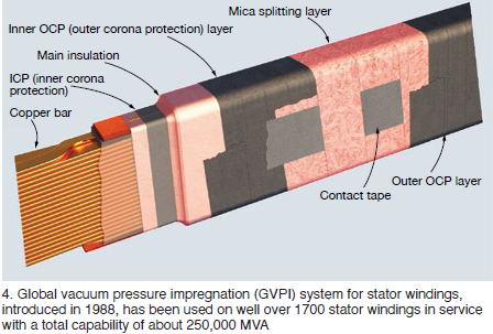
This is a well-illustrated presentation many O&M technicians can learn from. It addresses the failures of two different SGEN6-1000A generators serving gas turbines in a 4 × 1 combined cycle. The four units are characterized by globally vacuum pressure impregnated (GVPI) stator windings (Fig 4).
The first failure was on a 245-MVA, 15-kV machine after nine years of operation. An incorrect cable termination was used during plant construction. The spec called for unshielded cable, but 2/0 shielded cable was used and the shielding was not removed for the approximately 8 in. needed at termination. Because the shielding was not stripped back, it was within strike distance when the fault occurred. The current jumped into the shield rather than travel in the cable conductor, thereby overheating and failing the cable.
![]()
The second unit failed a stator-winding hi-pot after 10 years of operation. The test target was 33 kV, 2.2 times rated voltage, as it was for the first unit discussed above. In one phase a bar failed at 30 kV and in another phase a bar failed at 16 kV. Visual inspection showed an “insulation anomaly” on the top surface at core exit on both failed bars. Two other bars that had not failed also displayed the same insulation anomaly.
Several stator bars were extracted for root-cause analysis. A full rewind was performed on this stator. The slides did not comment on the difficulties of removing bars from a GVPI winding.
A CT scan on two failed bars showed signs of what appeared to be insulation cracking internal to the bar at the location of the ridges on both bars that failed the hi-pot, as well as the other two bars with ridges in the insulation. These flaws would be a very serious concern to the fleet of similar units, but the slides did not comment on this issue.
Nonmagnetic retaining ring in-service inspection drivers in 2020 and beyond
In-service inspection of generator retaining rings became an industry standard practice for plant owner/operators in North America and Europe during the mid-1980s, reminded Neil Kilpatrick, principal at GenMet LLC, a respected consultancy on generator metallurgical matters. Many 18Mn5Cr rings, the standard until that time, were found to exhibit significant stress corrosion cracking and most were replaced with 18Mn18Cr rings, which are not susceptible to SCC in water.
![]()
But the materials change does not mean you no longer have to perform periodic ring inspections, Kilpatrick said. You never know what might go wrong. He said the following are typical of the failure mechanisms which could cause concerns:
-
-
- Fatigue fracture (start/stop).
- Fault-related electrical damage to rings.
- Fault-related friction damage to rings (rubbing).
- Subsynchronous oscillation, with torsional fretting and fatigue cracking.
-
GE 7FH2 extreme vibration during LCI operation
Generator vibration observed during a turbine start using a LCI (load-commutated inverter) was “impossibly” high, the speaker said, showing comprehensive data plots on two slides. Focus of the initial inspection was on bearings (wiped? debris in lube oil?), LCI function, and lift oil (working properly?). LCI was later dropped from the list because it was shared with a sister unit onsite with no issue. GE suggested the cause might be turn shorts, based on its review of the data.
![]()
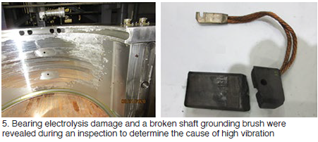
The engineering inspection and evaluation team identified electrolysis at the bearing (Fig 5), significant wear of hydrogen seals, broken shaft grounding brush, and a highly magnetized rotor (upwards of 450 gauss). Bearing repaired, shaft demagnetized to the extent possible with the rotor in place, a restart of the heavily instrumented unit was attempted. Seismic probes revealed an “impossible” 306 ips at 600 rpm.
Flux-probe waveforms showed a coil-to-coil short, with all the turns in one coil and half the turns in another being bypassed. The practical solution given time constraints: a rotor swap. Photos of initial findings when the unit was opened revealed deformed pole-to-pole connectors. Important to this discussion was that the normal pole crossover for a 7FH2 machine was not used when the generator was rewound previously by an alternative OEM and the replacement failed at about 700 starts and 11,500 hours.
Shop work included replacement of the two affected coils using pole-to-pole connectors of the generator OEM’s design. Problem solved.
Conclusions and lessons learned included these:
-
-
- Things can change completely from one start to another.
- Confirmed that turn shorts can cause exceptionally high vibration during an LCI start.
- Reinforced the need to inspect other units in the power generator’s fleet with a similar pole-to-pole connector.
- If it’s not broken, don’t try to fix it—referring to the change from the OEM’s hairpin pole-to-pole design which has worked well over the years.
-
SFRA study on generator stator re-wedging
The Sweep Frequency Response Analysis test generally is associated by plant personnel with the physical condition monitoring of transformer windings. It is an efficient way to detect displacement of the transformer core, deformation and displacement of the winding, faulty core grounds, collapse of partial winding, broken or loose clamp connections, shorted circuit turns, open winding conditions, etc.
![]()
In this presentation, the speaker presented three case histories and more than 50 slides to show the value of SFRA in determining when stator re-wedging is necessary. There’s still more work to do but the message is clear.
Wonder why wedge tightness is showing up in SFRA data? The speaker explained thusly:
-
-
- A loose wedging system opens clearances.
- Clearances permit movement of coils/bars to release installation/migration stresses.
- Movement opens gaps and contact points affect capacitance and inductive coupling, and resistance to ground.
-
Things to keep in mind when trying to apply the SFRA data include the following:
-
-
- Fresh paint affects readings; make sure all paint is cured before gathering data.
- Meaningful data are limited.
- The analysis presented is global in nature; local issues may not show.
- Coil/bar displacement is a dependent variable.
- The test cases presented are for hydrogen-cooled machines. In-slot partial discharge damage may affect readings for air-cooled generators.
- The test cases also are for 2-pole machines. It’s unknown at this time if the same patterns apply to 4-pole and hydro units.
-
AeroPac brushless-exciter flashover
It’s 0800 and the subject unit is synchronized with the grid; power is increased to 110 MW within the hour. Load is raised to 140 MW and the unit trips at 0915 on a loss of generator exciter voltage. The operator’s screen reads, “AVR fault.” No obvious issues are identified and the operators decide to re-energize the unit figuring the trip was “false.” But the unit trips again before it can be synched.
![]()
Inspection with assistance from a third-party services provider identified dust on the excitation generator, which was difficult to access. Molten metal was found in the diode wheel; it took three shifts to remove. Decision was made to remove the complete excitation generator housing.
The rotor shaft was damaged during the incident (very deep gouge) so it was pulled and sent to a shop for inspection, analysis, and repair. Electrical test results with the rotor out were satisfactory. Another observation: All six diodes failed but investigators were not able to determine how many failed before the incident. An alarm indicating diode failure was never received. Diodes had never before failed on any of the company’s generators.
Repairs: The portion of the shaft with the deep gouge was removed and a new piece welded it its place. The excitation generator and diode wheel also were scrapped. Shop discovery: A socket head cap screw was found wedged in the diode wheel casing and the connection from the diode wheel to the radial lead was melted in half. Electrical tests received a passing grade; the AVR was eliminated as the root cause.
With the RCA still in progress at the time of the presentation, the plant took the following actions:
-
-
- Planned to check the tightness of all bolts during every major outage.
- Purchased a handheld device to monitor diode condition; data would be collected monthly.
- Initiated work with the OEM on changing the type of filters for the air-cooled excitation generator.
- Planned to clean the excitation generator every four years and to replace the diodes and their hardware every 10 to 12 years.
-
7FH2 collector flashover event
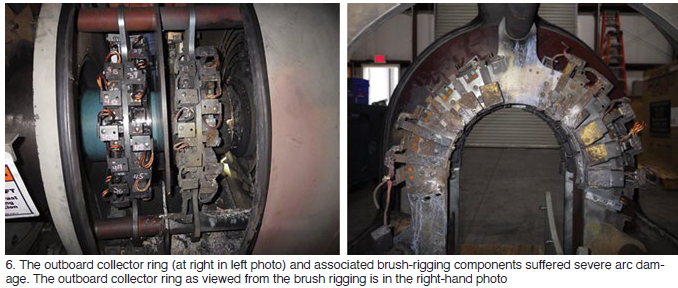
This presentation affords the rare opportunity to experience a collector flashover event, which lasted less than an hour, virtually. The generator damaged was a 239-MVA, 18-kV, hydrogen-cooled machine. Data, details in words, graphs of operating data, a dozen photos, etc, are provided.
![]()
The outboard collector ring and associated brush-rigging components suffered severe arc damage (Fig 6 left, outboard collector ring is at right in the photo): eight brushes detached completed, seven still attached by their pigtails were free of their holders, nine brushes remained stuck in their holders—attesting to the level of detail provided by the speaker. All 24 brush holders showed arc damage (Fig 6 right).
Repair scope included replacement of the following components:
-
-
- Entire brush rigging, including new holders and brushes.
- Both collector rings (the inboard ring could have been reused, however).
- Outboard collector terminal stud (the existing one had to be drilled out).
- Seal assemblies on both terminal studs.
-
Plus, shaft grinding was required to remove harden metal created by arcing.
Identification of the exact root cause of this flashover event was complicated because most of the evidence was vaporized during the incident. Insights gained during the inspection allowed elimination of the following possible causes as unlikely: short brushes, high brush vibration levels, inadequate ventilation, and ambient air contamination.
Among the contributors to this specific collector flashover were believed to be generally low current densities in the brushes, ineffective periodic cleaning of brush holders by contract personnel, poor contact between brush terminals (pigtails) and the outboard collector yoke assembly, and improper orientation of brush holders relative to the collector ring. In brief, the speaker believed the brush holders had outlived their useful lives.
The speaker offered the following characteristics of good collector assembly performance:
-
-
- Continuous contact of brush to collector ring.
- Proper brush-to-collector ring contact pressure.
- Good collector-ring surface film condition.
- Limited selectivity.
-
A proven maintenance approach to assure good collector assembly performance focuses on these points:
-
-
- Routine checks of collector assemblies with rounds on each shift.
- Weekly checks with the enclosure covers removed—including visual inspection, verification of no abnormal brush vibration, and confirmation of brush freedom of movement within the holders.
- Monthly, measure brush currents. Compare these to those from the preceding month to identify any obvious current selectivity.
- Identify and log specific deficiencies, if any, identified with the prescribed maintenance approach.
-