
Presentations made by National Electric Coil, MD&A, AGT Services, and Siemens Energy to owner/operators participating in Weeks Three and Four of the virtual GUG2020 conference are summarized below. You can access the PowerPoints submitted by the first three vendors on the Power Users website. The Siemens presentations are posted on the company’s Customer Extranet Portal (CEP). For help in locating them, contact your plant’s service representative.
NEC
Corona in HV stator coils: Theory, causes, repair, and laboratory prognosis
W Howard Moudy, director of operations for National Electric Coil, is a frequent presenter at user group meetings. His goal here was to help plant personnel better understand what corona is, the damage it does, how to identify its presence, and the need to repair the damage it causes early, to avoid the possible need for a coil replacement.
But first, a brief backgrounder on the terminology, extracted from an article written for CCJ by Donald Selkirk, PE, of SaskPower several years ago. The terms corona and partial discharge (PD) are commonly used interchangeably in the electric power industry, he wrote. However, this is not correct.
![]()
Both corona and PD are electrical discharges that occur in high-voltage rotating machines (HVRM) when the strength of the applied electric field is great enough to cause ionization.
The IEEE Standards define corona as a “luminous discharge due to ionization of the air surrounding a conductor caused by a voltage gradient exceeding a certain critical value.”
PD is not necessarily luminous or visible. Further, PD may not occur adjacent to an energized conductor and need not occur in air or gas. Additionally, a corona discharge may bridge the entire gap between energized conductors.
Moudy continued: Corona is a surface phenomenon (a “glow”), he said, that leaves its distinguishable mark on winding surfaces, both in the cell and end-winding portions of HVRMs. It is often caused by insufficient clearances between surfaces having different electrical potentials.
Corona also may be attributed to inadequate functioning of the gradient portion of the outer corona protection (OCP) wrap encapsulating stator bars (Fig 1). Erosion of the OCP, he continued, can develop from inside the coil when the ground-wall insulation near the OCP is of poor quality. Mica is a material that may best inhibit corona attack on ground-wall insulation.
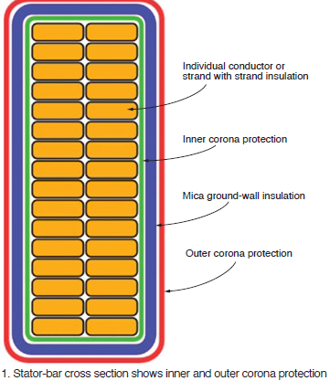
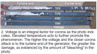
The insulation binder is attacked first, followed by the conductive fillers of the OCP material, which may be destroyed. This allows the corona to reach the OCP surface, where it is easy to recognize (Fig 2). Moudy noted that OCP repairs made prior to deterioration deep into the ground-wall insulation are most successful. Given reasonable access, he said, future deterioration in the area of repair can be prevented. Then the prognosis for long-term reliability is very good.
HV generator stator ground insulation repairs
This presentation by National Electric Coil’s W Howard Moudy, director operations, and Gary Slovisky, director of field service, discusses in meaningful detail two case histories—one concerned with the repair of ground-wall insulation, the other with OCP (outer corona protection) repair. The second is a sequel to Moudy’s first presentation (immediately above).
![]()
Before committing to a repair, the speakers began, there are things you should know—including the following:
-
-
- Understand the cause of the failure.
- Determine the full extent of damage and the suitability of undamaged components.
- Identify the repair options.
- Consider the practicality of the repair options identified and their associated risks, and the prognosis in terms of reliability.
-
Participation and guidance by experienced personnel with a bit of wisdom is essential for a successful outcome, Moudy and Slovisky said. Keep in mind that access and space often are the greatest obstacles in making repairs in the field. Creativity, patience, and experience are essential to overcoming these obstacles.
The root cause of damage to ground-wall insulation in the first case history was a rotor fan blade failure attributed to high-cycle fatigue. One of the 16 fan blades failed near its base but not at the weld joint. The liberated fan tip ring damaged the stator. The generator was relatively small, rated just under 22 MVA. The incident was characterized as a generic OEM design problem. The replacement 13-blade fan was machined from one block of ASTM 4340 alloy steel (no fan tip ring).
Interestingly, some owner/operators of air-cooled condensers equipped with fans having an even number of blades, identified with this problem. Their issues were resolved as well by transitioning to a fan with an odd number of blades.
These three repair options were considered:
-
-
- Repair failed and damaged coils in-situ and onsite. This offered the shortest delivery time and lowest price, but the lowest evaluated reliability.
- Factory repair and reinsulate the two failed coils; repair other damaged coils onsite. This option was penalized by a slightly longer delivery time than repair and about twice the cost of repair. However, it was less than one-third the rewind cost and offered a good evaluated reliability.
- A complete stator rewind was characterized by longest delivery time, highest price, and highest evaluated reliability.
-
The first option was selected. Presentation illustrates how the ground-wall insulation was repaired successfully, step by step.
The second case history reviews OCP field repairs to a pumped-storage hydro generator and to a generator for an F-class gas turbine. Critical to achieving a successful OCP repair are the following:
-
-
- Expertise and skilled labor.
- Use of materials of the highest quality and of proven engineered processes.
- Assuring an appropriate interface with the ground plane (core).
- Thorough mixing of semi-conductive and gradient coating treatment materials.
- Application of the gradient coating in a manner to assure proper/adequate overlap with semi-con coating.
- Ensure adequate cure time.
-
MD&A
Preparing generator rotors for cyclic duty
James Joyce, MD&A manager of generator repair operations, set the scene with his opening statement: “The impact of cyclic operation on ac generators is significant. As more units transition from baseload to cyclic duty, the thinking behind generator maintenance and repairs needs to adapt.”
Keep in mind that baseload units operate under creep conditions—that is, constant stress—while cyclic units are challenged by the fluctuating stresses consistent with fatigue conditions.
![]()
Major contributors to increased wear on generator rotors in cyclic service, he continued, are these:
-
-
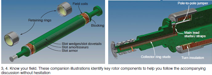
- Different rates of expansion and contraction of rotor components in close proximity to each other that are made from different materials. Examples include copper coils, insulation, and steel forging (Figs 3 and 4).
- Expansion and contraction of the retaining rings caused by centrifugal force.
-
Recall that heating of the rotor winding generally is the limiting feature in generator design. Thus, generators cooled by hydrogen, a more-efficient coolant than air, and are smaller than air-cooled units of similar output and issues related to the expansion and contraction of components are not as severe.
Important to note, Joyce said, that generator manufacturers are under increasing pressure to reduce costs and necessary decisions on conductor cross section, insulation thickness, the amount of steel in the core, etc, negatively impact a generator’s ability to absorb the increased mechanical and electrical stresses of cyclic duty. This puts pressure on O&M personnel to operate their machines within limits suggested by designers to assure the desired levels of reliability and availability can be achieved.
Joyce’s presentation focused on case histories illustrating the effects of cycle duty on the generator fields for a 450-MW hydrogen-cooled unit, a 200-MW hydrogen-cooled unit, a 300-MW air-cooled unit, and an 80-MW air cooled unit. You can learn a great deal from the PowerPoint because the speaker shares the planned work scope for the shop visit, what was found during the inspection, emergent work required, solutions selected, etc.
Highlights include the following:
-
-
- Cracked blocking required replacement with an enhanced design to prevent crushing and delamination.
- Replacement of original Nomex turn insulation with a glass laminate material which does not absorb moisture to the extent that Nomex does.
- Modification of a full-length slot amortisseur, springs, and creepage blocks to accept a top hat pin which locks all three components together, thereby preventing the springs under the slot amortisseurs from migrating during operation.
- Replacement of original slot armor with Teflon-coated Nomex. Note that the relative movement of the copper coils during load cycling can lead to abrasive damage to the slot armor. The Teflon coating provides a slip plane to mitigate this.
- The original pole-to-pole connectors were susceptible to low-cycle fatigue as the copper coils expanded and contracted during cyclic operation. They were replaced with an improved design more capable of handling the additional stresses associated with cyclic duty.
- Copper deformation from cycling dictated coil replacement. Plus, there were broken main leads not normally seen in situations involving high cycles; they too were replaced. New retaining-ring insulation also was installed, the replacement with a Teflon slip plane to prevent the end-winding top turns from deforming while expanding and contracting axially as they heat up and cool down.
-
Generator findings and case studies
James Joyce’s second presentation provides valuable information for all involved in generator-maintenance decision-making. You’ve heard at user-group meetings about outage extensions to deal with emergent work and may be wondering just how often such incidents occur. Joyce shares MD&A’s experience from the 18 months preceding his presentation Dec 3, 2020 to illustrate how important it is for you to operate your generator within the bounds of the OEM’s recommended practice, review operating data with a keen eye, conduct appropriate tests periodically, and to continually plan for the outage ahead—all this to minimize the number of surprises at the next overhaul.
The manager of generator repair operations said that most fields that come into MD&A’s shop fall into two categories: rewind, or rings-off inspection with a defined scope that does not involve a rewind—such as blocking mods, deep cleaning, or simple testing and inspection.
![]()
In the last 18 months, he said, 70% of the units that came into the shop were scheduled ahead of time. The rest were the result of a forced outage. In that latter group, about 12% participated in a field-swap program to minimize outage time. Roughly one-quarter of the scheduled visits required an outage extension because of emergent work (expansion of the original work scope).
Analyzing the root causes of field rewinds, Joyce said 46% of the generators had to be rewound because of a shorted turn or ground fault, 38% because of a main lead or mechanical failure (the latter category includes failed blocking, copper mushrooming, etc), and 12% because of contamination (such as foreign material blocking ventilation passages) that could not be removed. The remaining rewinds were age related.
Joyce concluded his presentation with two case studies, one involving a collector ring failure, the other damage attributed to loss of lube oil. The first resulted from a flashover between the brush rigging and field forging. Once the flashover occurred the collector-ring insulation was compromised, allowing a ground fault from the collector rings to the field forging. Many photos illustrate the extensive damage incurred.
The field winding was unaffected by the flashover. This allowed removal of the damaged section at the end of the rotor and installation of a stub-shaft in its place. Machining of the turbine end journal and oil-deflector surfaces was part of the rework required. Successful inspections and high-speed balance confirmed the field was fit for duty.
The lube-oil failure experienced during startup after a maintenance outage did considerable damage. It occurred because the lube oil to the generator bearings was inadvertently shut off. The incident screamed for attention to detail on the deckplates, the use of checklists, and multiple pairs of eyes on everything.
The resulting bearing failure caused the shaft to drop about 200 mils. The rotating blower hub blades then contacted the stationary housing and shredded, sending the stainless-steel blades throughout the unit. Repair work included machining and weld restoration of journal and seal areas to eliminate hardness, installation of a stub shaft, a rewind and replacement of all insulation components, and blower replacement.
AGT Services
GE GT- and ST-driven generator field repair needs
AGT Services’ Jamie Clark has been on a mission for the last couple of years, presenting at the annual meetings of all major users groups to alert owner/operators about the significant increase in generator failures his company and other service firms are seeing. Clark’s thoughts echoed those of MD&A’s James Joyce in his presentation a week earlier, “Generator findings and case studies” (see above).
![]()
Both Clark and Joyce agree that the failures experienced today are related in large part to unit cycling (in particular, those machines designed for baseload service) and age, with lapses in attention to detail during inspection and maintenance contributing.
Clark began his presentation with a chart illustrating the dramatic increase in the number of starts experienced by a combined-cycle plant in Maine over the last decade compared to the start stats for the facility’s first eight years of service. An informal survey that he conducted at a recent meeting revealed a 50% increase in the number of starts among 7F owner/operators. That was an interesting factoid because about half of “planned” projects that AGT Services has been involved in lately have resulted in emergent work. Another 14% of the surveyed users said their starts had doubled, or more than doubled, over the last 10 years.
AGT is seeing more unplanned stator rewinds than ever, Clark continued. Same is true for field rewinds, he added, with some of those resulting from stator failures.
Clark then highlighted the primary areas of the stator affected by cycling, including the following:
-
-
- End-winding vibration/loosening, noting the higher risk for strand-to-strand series connections.
- Core-looseness impacts—such as keybar rattle/belly bands and loss of core compression.
- Slot support system—including wedge system and side packing/ripple springs.
-
The speaker stressed that all stator parts are designed to work together as a system. Example: Bellybands restrain keybars and when loose allow keybars to “rattle” producing particles of iron oxide. Add in some oil and you have greasing that lubricates the connections, further compromising tightness.
Clark’s extensively illustrated presentation next walks you through the primary field components affected by age/cycling (or design), focusing primarily on GE 7FH2 and 324 generators. Below is a list of the topics he covers. One or more has to be of sufficient interest to warrant a review of slides on the Power Users website. [link]
Slot component migration
-
-
- Creepage block
- Amortisseur springs
- Slot armor deterioration (birth or prior repair defects)
- Turn insulation
-
Distance blocking movement
-
-
- Axial blocks
- Radial blocks
-
End turn insulation migration
Copper distortion
-
-
- Main leads, crossovers
- Elongation/foreshortening
- Fat copper in the slots
-
Braze design/failure
Cracked brazes at corners and on crossovers and leads
Collector systems
-
-
- Leaking stud seals
- Collector ring/brush life
- Field ground detector inoperative
-
Siemens Energy
Case studies: Cycling impacts on generators
Alejandro Felix, Siemens Energy’s manager of generator service engineering, focuses in large part on the effects of flexible operation on stator end windings and then discusses the OEM’s innovative technologies to address flex-operation needs. For rotor components these include new designs for J straps and pole crossovers. For the stator, new rewind designs are more capable of absorbing axial thermal expansion of the coils. The presentation concludes with a look at Siemens’ service solutions to support flex operation.
Third-harmonic stator ground protection
Tony Cararano, solutions engineer, digs into the details of third-harmonic voltage and how to assure 100% stator ground protection not assured by adhering to IEEE standards. Topics discussed include 59N neutral over-voltage, 27TN third-harmonic neutral under-voltage, and 64S subharmonic voltage injection. Three case studies provide valuable insights.
Hi-pot testing approach
Jim Lau, expert engineer and one of the industry’s most highly regarded electrical engineers, provided a backgrounder on high-voltage testing, covering both ac and dc tests. Dielectric evaluation, preparations to test insulation resistance and polarization index, the value of pass/fail dc hi-pot testing, partial-discharge testing, low-voltage power-factor testing are among the topics reviewed.