While the industry makes progress towards the fully connected, largely automated powerplant with a meta-organization of onsite staff, remote monitoring and diagnostics (M&D) assistance, and market delivery setpoints, there are some serious and costly gaps that are overlooked in data links and industrial communications. According to Jeff Downen, business owner, Black Start LLC, these gaps are often revealed and corrected during commissioning.
Some root causes of the gaps include the following:
- Scope irregularities between the automation platform’s OEM and the plant’s EPC, often based on technology design and concepts a decade or two out of date.
- Insufficient communication between vendors while designing communication links and network paths, usually reflected in the I&C drawings and configurations.
- Quantum leaps in data points being captured, transmitted, and monitored in sophisticated graphics with data speeds at the gigabit level.
- EPCs using electrical engineers to do the design, rather than I&C/DCS engineers with IT networking experience.
- Engineering and procurement documents often don’t address communications protocols, network speeds, connection types, and media conversion.
As Downen said in an interview, “All of these software packages and hardware procured from different vendors are designed so they can communicate, but someone still has to troubleshoot and integrate the systems so they will.”
Here are some of the most common issues Downen and his team encounter during commissioning while working directly for the EPC:
Improperly matched communications speeds. One example is multiple issues with incorrect baud rates on the serial links and 100/1000 base connections for fiber and Ethernet. An example: SEL (Schweitzer Engineering Labs) 2730 small form-factor pluggable (SFP) ports designed as 1000 base fiber, and designed to connect with Emerson-provided EtherWAN media converters that were 100 base, are incompatible.
Media and cabling. Single- and multi-mode fiber issues crop up from the engineering and procurement phases. Example: A generator step-up (GSU) annunciator panel’s initial design called for an SEL serial device for a Modbus remote terminal unit (RTU). However, the network path only allowed a Modbus TCP/IP via the routers over port 502 and also needed a null-modem serial cable.
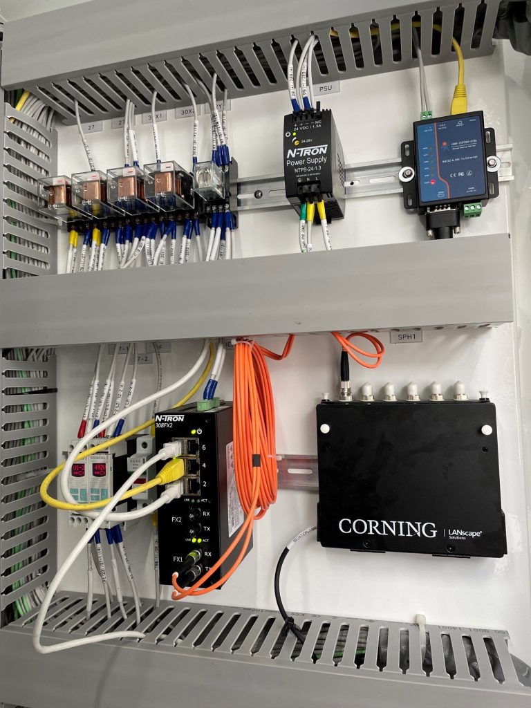
This was corrected by adding a mini-network for media and protocol conversion as shown in the photo. Port 502 is the Modbus protocol widely used for TCP/IP communications, allowing Modbus data links and traffic to pass through an IP network.
Another example involved the SEL discrete programmable automation controller (DPAC). The real-time automation controllers (RTAC) in the switchyard were using SEL 273A cables and communicating over a distributed network protocol (DNP). The serial nature of the protocol prohibits the cable from allowing traffic between the devices because the request-to-send (RTS) and clear-to-send (CTS) pinouts on the selected cable were incompatible. For non-IT types, RTS and CTS are data flow control mechanisms which are part of the RS232 standard connector.
This issue was corrected by changing over to the SEL protocol but would never have been an issue if SEL 272 cables were selected in the first place; it has the correct pinout.
IP addressing and subnets. Devices on the same network often are not configured properly, along with incorrect gateway assignments, port configuration issues, and the same subnets being used on the adjacent sides of a field router. An example that Downen found was an Ovation DCS with Ethernet link controller cards on the same subnet with identical IP addresses as some of the relays on an opposing network (each side of a router). This can be corrected by changing either side of the router’s respective devices. An example: RTACs and relay network settings to be changed out by reconfiguring the router files and the DCS programming. Both are costly and time-consuming tasks.
Some ports, especially 80 (HTTP), 502 (Modbus), and 23 (Telnet) are not properly understood during design and end up being used incorrectly on a majority of devices for serial tunneling, web interfaces, and Modbus communications.
Spares and equipped spaces with blank equipment for a plant’s future use typically have a default IP address but are still connected to the same network in use by the plant, causing network collisions, or loss of information and errors while communicating. This event can be witnessed when a master or client device is confused because an identical subnet is on the other side of the field router with similar device IP addresses.