
High-temperature pressure sensors and accelerometers rarely get much attention when they are doing their jobs. But when a combustion dynamics channel goes noisy, a cable loosens, or a monitoring system starts throwing spikes, the consequences can move quickly from nuisance to risk.
That was the practical takeaway from Dave Martin, business development manager at PCB Piezotronics, during CCJ’s recent webinar on high-temperature sensor systems for turbine monitoring. Addressing plant personnel responsible for reliability, emissions, and outage planning, Martin spent less time on sensor theory and more on the realities of field performance emphasizing signal quality, proper installation, and disciplined troubleshooting.
For gas-turbine users, the starting point is combustion dynamics. Martin described combustion instability—still called “humming” by some veterans—as pressure oscillations in the combustor that can damage hardware, shorten component life, increase fuel consumption, and in the worst case force an unplanned outage. Monitoring those oscillations gives operators another way to protect the machine while also supporting combustion tuning, emissions compliance, and unit availability. In his words, the value goes well beyond emissions alone. Martin said one large power producer realized millions of dollars in fuel savings over several years after getting combustion-dynamics systems working properly and upgrading weak legacy installations.
The webinar, viewable below, also reviewed how combustion-dynamics sensing has evolved over time. Early remote and close-coupled configurations relied on tubing, purge systems, and inline or near-line sensors. While these arrangements functioned adequately, they also introduced several paths for compromised data. If purge tubing was not kept clean, dry, and properly nitrogen-purged, unwanted frequencies could enter the signal. Vibration in the tubing and prolonged exposure to high temperatures added further opportunities for measurement issues.
By comparison, sensors mounted directly on the turbine at the combustor avoid many of those complications. Designed to withstand temperatures approaching 1400F, these on-turbine sensors eliminate the need for purge systems, reduce maintenance requirements, and provide clearer signals. Martin noted that major OEMs now widely adopt these sensors for precisely those advantages.
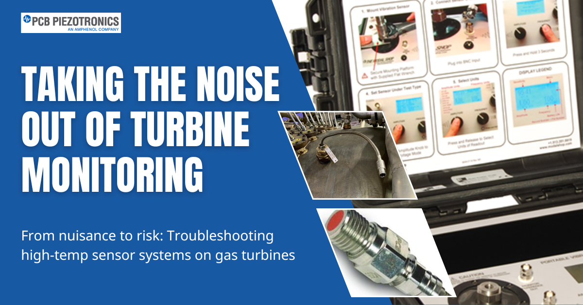
Installation details matter. Sensors are typically mounted on the combustor casing, with the tip positioned either at the casing surface in a recessed mount or at the liner surface in a flush mount. Mounting methods include clamp nuts, screws, Swagelok fittings, and threaded sensor bodies torqued to specification. Martin showed examples from GE 7FA and Siemens 501F applications, along with cabinet hardware used in newer combustion dynamics monitoring system retrofits that replace older purge-box arrangements. The hardware chain itself is straightforward: high-temperature dynamic pressure sensor, extension cable, differential charge amplifier or signal conditioner, power supply, and the monitoring or data-acquisition system. But getting each link right is what determines whether the operator sees useful information or chases bad indications.
Martin also spent time on high-temperature accelerometers, which face a similar challenge. Standard IEPE devices are constrained by built-in electronics and generally cannot survive turbine hot zones. High-temperature charge-mode accelerometers move the electronics out of the heat and, in turbine service, are typically specified in differential charge designs to improve noise rejection. The point, he said plainly, is to keep noise out of the signal. Differential architectures cancel common-mode electrical interference that can plague charge systems in harsh plant environments. For users dealing with vibration monitoring near hot sections, that design choice is not academic; it is often the difference between a trusted channel and a misleading one.
Martin’s troubleshooting guidance was among the webinar’s most practical takeaways. When a pressure-monitoring channel starts acting up, his first advice is not to blame the sensor. In his experience, high-temperature sensors rarely fail under normal operating conditions. More often, the issue lies somewhere along the measurement chain—most commonly in the cable. Loose connections, damaged extension cables, sections that have melted after resting on hot surfaces, and grounding errors are frequent sources of trouble.
For pressure systems, Martin recommends checking the integrity of the chain with a charge/ICP simulator connected at the extension cable. This allows technicians to verify the signal path from the cable through the charge amplifier to the data-acquisition hardware. If that pathway checks out, only then does it make sense to suspect the sensor and send it out for testing. He offered the same practical advice when addressing CDMS noise and signal spikes: start by looking for grounding issues and loose connection
The Q&A session reinforced the webinar’s practical, field-focused tone. Martin noted that PCB supports legacy turbine applications like the GEV Frame 6B and can assist plants in identifying replacements for Meggitt Vibro-Meter components, often providing drop-in alternatives. He also challenged the idea of fixed replacement intervals for high-temperature sensors, arguing that if sensors are removed and handled properly during outages, they should not be retired simply because a calendar says so.
For plant managers and OEM engineers, the broader takeaway from the webinar was clear: improving turbine monitoring does not start with purchasing more hardware. It starts with understanding the entire sensing chain, minimizing avoidable sources of noise, and approaching installation and troubleshooting as core reliability tasks rather than routine instrument housekeeping. For more detail, view and share the webinar recording. CCJ