Kings Mountain Energy Center
Owned by Carolina Power Partners LLC
Managed by CAMS
Operated by NAES Corp
475 MW, gas-fired 1 × 1 M501GAC-powered combined cycle, located in Kings Mountain, NCPlant manager: Sean Spain
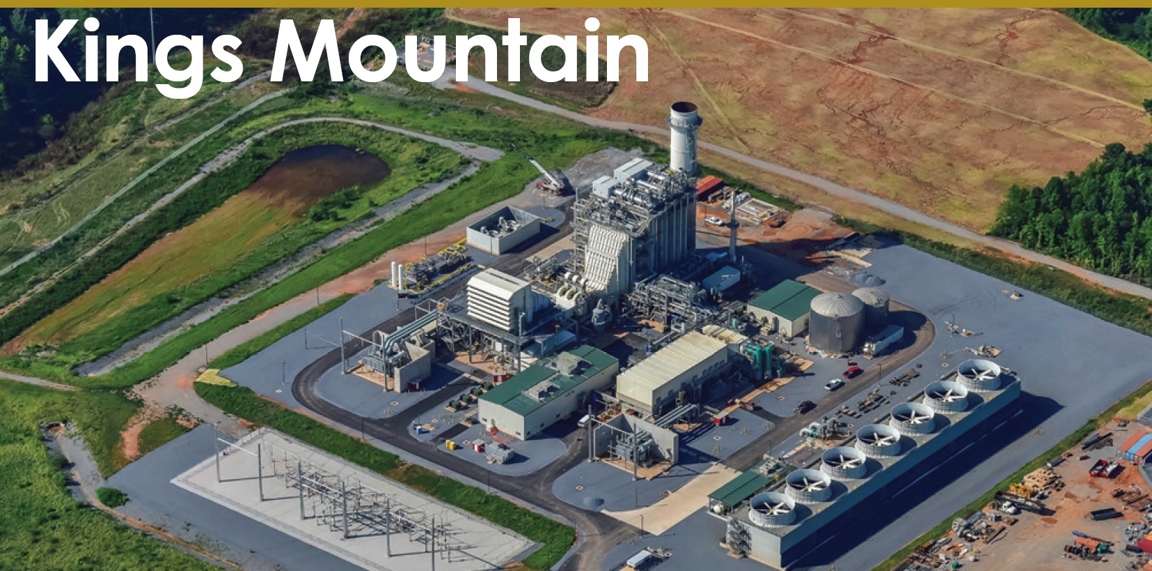
Storm shelter protects staff during weather events
Challenge. A mid 2020 tornado that touched down within a mile of Kings Mountain (KMEC), plus several storms that spawned high winds, encouraged a reassessment of the plant’s capabilities for personnel protection. There was an emergency protection plan, of course, but staff believed it could do better.
The best place to shelter in the existing building was a small room with no windows on an exterior wall. However, it was difficult to accommodate the entire staff safely in that space.
Solution was to implement a Management of Change action to build a tornado shelter. Plant personnel worked with an engineering group to create a blueprint for an independent structure adjacent to the plant (Fig 1) and sent it out for bids. The contractor selected built the specified shelter in its shop and poured the concrete pad.
Once the concrete slab had cured, KMEC O&M staff engaged a crane to install the prebuilt shelter on the pad. Plant electricians installed the lighting in the shelter. Finally, the site’s emergency action plan was updated and a tornado drill was conducted.
Result. KMEC now has a designated shelter to protect personnel during possible future weather events.
Project participants:
The plant’s entire O&M team
‘Magnetite catcher’ helps prevent sticking issues with steam-turbine valves
Challenge. KMEC uses its steam-turbine bypass system for steam-system control during starts, shutdowns, upsets, and other situations when the turbine is not available. Bypass valves are of the Fisher ™ TBX pressure control type with a “flow under the seat” design. Two of the plant’s three bypass valves have experienced sticking during a vast majority of the starts—both hot and cold—since commissioning in 2018, causing upsets and inconveniences.
Fisher was contacted to troubleshoot the problem and run diagnostics on the valves and their actuators. Interestingly, the valves functioned satisfactorily during outage diagnostic testing.
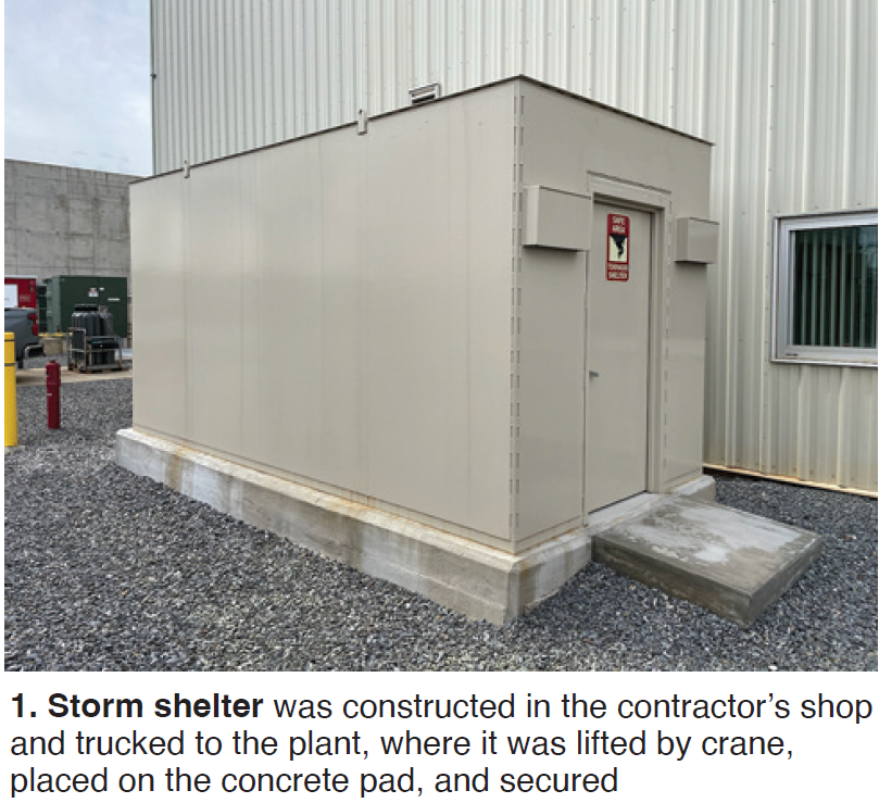
Additional investigation revealed a possible issue with magnetite from the steam system causing operability issues with this valve design. Plant staff contacted other facilities with valves of the same type and learned the sticking issue could be resolved by using “magnetite catchers” (Fig 2) on hot-reheat (HRH) and main-steam (HP) bypass valves.
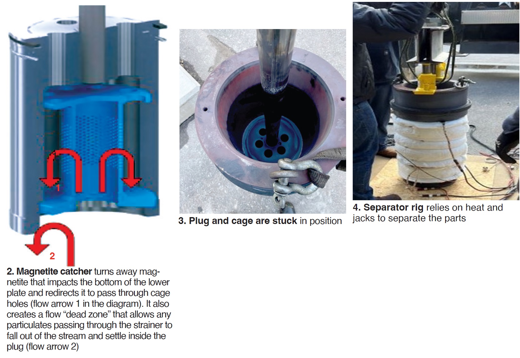
Solution. When first removed from the valve body, the plug, stem, and cage assembly couldn’t be separated because of the magnetite (Fig 3). But after heating the cage and using hydraulic jacks (Fig 4), the parts were separated.
A valve services company was engaged to retrofit spare sets of HP and HRH bypass valve trim. This was done in four days during a routine outage.
Results. Subsequent to the install of magnetite catchers, several plant cycles have been performed with no sticking issues on the upgraded valves. Current plans are to open and inspect the valves after three years of service to determine overall condition and the amount of magnetite captured.
Project participants:
The plant’s entire O&M team
Improve SCR maintenance to reduce emissions, cost
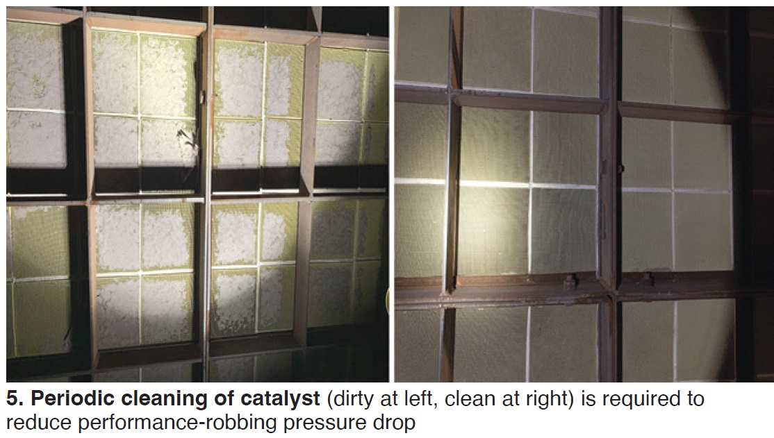
Challenge. Since commissioning, KMEC has had various challenges in maintaining NOₓ and CO emissions. Staff quickly worked through short-term fixes to achieve better results, but some long-term recurring challenges are associated with increasing pressure drop across the catalysts caused by airborne particles of insulation from the duct-burner area impeding gas flow (Fig 5).
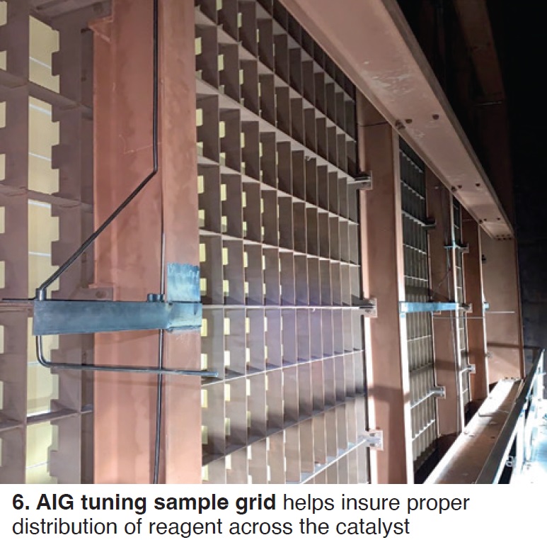
Another problem: An increase in SCR injection-blower discharge pressure attributed to ammonia deposits and the build-up of insulation in the injection nozzles. A tuning grid was installed to help adjust ammonia injection in sections of catalyst so affected (Fig 6).
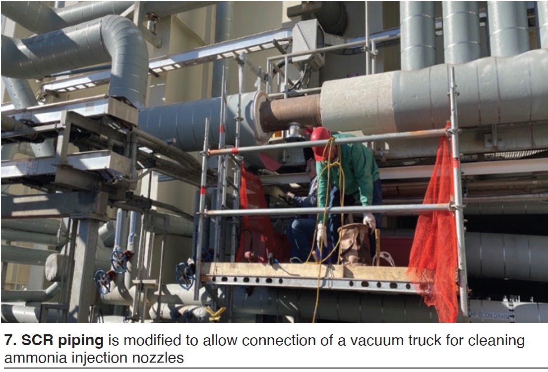
Solution. During planned outages, CO and SCR catalysts are cleaned to reduce performance-robbing pressure drop. Also, a flange was installed in the SCR injection-blower discharge piping to allow a vacuum truck to connect to the injection piping and remove deposits in the injection nozzles (Fig 7).
To better gauge SCR catalyst performance, a sampling grid was installed on the downstream side of the SCR catalyst modules. It provides an array of 18 sampling locations—three wide in each of the six AIG (ammonia injection grid) zones.
Results. KMEC’s ability to reduce emissions and adhere to permit limits has been improved. Plus staff can perform SCR maintenance better and faster during planned outages, thereby helping to prevent unplanned outages. Another benefit is reduced ammonia consumption and associated cost.
Project participants:
The plant’s entire O&M team