
Webinar effective for technology, regulatory updates

Many powerplant supervisory personnel who could benefit from attending user group meetings often do not get to the annual conferences covering their gas turbines. Some have never gone. You know the usual reasons: internal meetings, no travel budget, short-staffed, etc.
For those who attend at least every other conference, 12 or 24 months is a long time to go between meetings and many things you should be aware of, but might not be, can happen during that time. Examples include new regulations, new/revised OEM technical information letters, best practices, equipment upgrades, etc.
Pat Myers, a member of the 7EAUsers Group steering committee , understands well the challenges of managing a multi-unit powerplant while trying to keep up with the seemingly endless number of equipment, personnel, ownership, and regulatory changes that characterize the generation sector of the electric power industry today.
Example: In addition to his day job as plant manager of American Electric Power Co’s Ceredo Generating Station, Myers was selected to head a special corporate committee charged with reviewing and upgrading, where necessary, AEP’s practices for the safe handling and combustion of natural gas. This included compliance with NFPA® 56, “Provisional Standard for the Commissioning and Maintenance of Flammable Gas Piping Systems,” which was being developed in parallel with the AEP initiative.
 Myers, who spent more than two decades in the employ of a major gas transmission company before joining AEP, recognized that NFPA 56 would be a “game changer” regarding traditional practices of handling and burning natural gas at powerplants. He believed it was important for the industry to understand the safety standard’s requirements as soon as it was made public.
 Owner/operators of 7B-EA engines worldwide were invited to participate at no cost in the user-only event, which was sponsored by Allied Power Group LLC,Houston. There were 88 owner/operators signed on when the webinar started and 53 were still connected when the “meeting” ended nearly two hours later. The broadcast had been scheduled for one hour but the presentations typically ran 15 minutes rather than the planned 10 and Q&A averaged more than 10 minutes per speaker.
Host for the webinar was Amy Alix, an engineer in Progress Energy Florida Inc’s Combustion Turbine Operations group, and member of the 7EA User Group’s steering committee. CCJ Senior Editor Scott Schwieger was responsible for the behind-the-scenes work in the “broadcast booth.” The webinar was not recorded.
The technical program was as follows:
- “NFPA 56, What You Need to Know to Protect Personnel and Property,” Mike Bethany, lead mechanical engineer, CEC Combustion Services Group, Cleveland.Bethany, CEC President John Puskar’s back-up on the NFPA 56 committee, is an expert in gas purging by virtue of his onsite involvement in dozens of such projects.
- “7EA R2 and R3 Bucket Rail Loss Repair Options and Preventive Measures,” Aaron Frost, technical director, Allied Power Group LLC,Houston. Frost is one of the industry’s top experts in the repair of HGP parts.
- “Control System Upgrades,” Glenn Corbiere, operations supervisor, Stony Brook Energy Center, Massachusetts Municipal Wholesale Electric Co (MMWEC), Ludlow, Mass. Corbiere profiled the conversion of four 7Es from Mark II control systems to PLC-based controls and one 7E converted to DLN-1/Mark V in 1993 to PLC-based controls.
- “Onsite Hot Section Fir Tree Build-up,” Pat Long, engineer, Calpine Corp’s Turbine Maintenance Group. Long has spent three decades on the
 deck plates doing what was necessary to get plants back in operation. This was the first time he had participated in a user group meeting.
- “Bucket-Rock Solution: Reduce Turning-Gear Speed,” Ken Knecht, maintenance foreman, Beluga Power Plant, Chugach Electric AssociationInc. Knecht, a millwright by trade, has been repairing, and supervising repairs to, gas turbines for 30+ years. This was the first time he had participated in a user group meeting.
NFPA 56.
CCJ has followed the development of NFPA 56 since Myers first brought it to the editors’ attention more than a year ago. Early details on the safety standard appeared in both the journal and CCJONsite, an electronic letter that reports on developments at user-group meetings. Access the 2011 Outage Handbook at www.ccj-online.com and read “NFPA 56 a ‘game changer’.”
Bethany’s presentation reviewed much of the material in that article and went a step further by telling webinar participants what they should do now that the provisional standard was “official.” First, he hammered home the point that OSHA compliance starts with a consensus standard being in effect. Non-compliance with a consensus standard usually is the basis for an OSHA citation.
While the designation “provisional standard” may appear to have only “baby teeth,” that thought couldn’t be further from the truth. It only means that the standard’s development was expedited. The possibility of an OSHA citation for not heeding it is very real.
For those who were caught unawares and take issue with some of the standard’s requirements, note that NFPA’s automatic revision cycle has already begun and new comments are being accepted. This standard will become a “code” as soon as a state adopts it into law.Connecticut, where the fatal gas explosion at the Kleen Energy combined cycle occurred in February 2010, is one state likely to do that.
Bethany urged everyone to buy a copy of the code at www.nfpa.org ($33.75) and read it. Next, develop the required implementation plan for your operation. This is very important: You must have a plan and it must include procedures, a hazard review process, and training. More specifically:
- Procedures for the retrofit of systems to enable safe purging and reintroduction of gas.
- Detailed plans for routine gas practices.
- Checklists for hazard review processes.
- Training of employees and monitoring of contractor personnel.
Be prepared, the expert noted. The implementation plan will impact regular operational activities and organizational and personnel behaviors will have to change.
To learn more, email CEC’s Puskar (jpuskar@combustionsafety.com) for a copy of his whitepaper summary highlights of NFPA 56.
Bucket rail loss
Allied Power Group’s Technical Director Aaron Frost reviewed rail-loss repair options and preventive measures following the Q&A onBethany’s presentation. Although Frost’s focus was rail loss on 7EA R2 and R3 buckets, the wear issue is problematic for owners of other engines as well—such as Frame 6B and 7FA+e R2 and R3 buckets and 501FD R3 turbine blades. Thus many users outside the 7EA community can benefit from what he said.
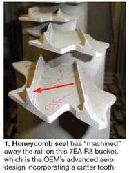 The problem, Frost said, is that in many instances the honeycomb becomes a cutting tool and machines away the tip rail of shrouded turbine buckets/blades (Fig 1). He noted that GE Energy uses a cutter-tooth design for its shrouded buckets, whereas Siemens does not. But in either case, he continued, the chance that the honeycomb machines off the bucket rail or that the bucket rail wins is the same (Fig 2).
The crux of the wear problem, Frost said, is that the Haynes 214 (GE) and Hastelloy X (Siemens) honeycomb materials oxidize over time, forming either an aluminum oxide or chrome oxide surface scale during exposure to high temperatures. Both oxides are abrasive and capable of machining away bucket/blade rails (Fig 3).
Allied’s proven method for preventing such damage is to coat rails with an abrasive plasma-deposited aluminum oxide coating (Figs 4, 5). This makes the bucket/blade the cutting tool instead of the honeycomb. It also eliminates the need for cutter teeth, improves seal effectiveness, and protects the side of the rail against wear associated with rotor movement during startup and shutdown. Finally, the removal of cutter teeth improves long-term shroud and airfoil creep life because of the reduction in weight.
Houston-based Allied, long a supporter of user-group activities, sponsored the 7EA User Group’s first webinar.

Control system upgrade
Corbiere told webinar participants that Stony Brook has been well cared for throughout its three decades of service. MMWEC management understands that equipment must be upgraded and replaced for a generating facility to maintain its value. So it came as no surprise when budgets were approved for replacement of the original Speedtronic Mark II control systems on four of the plant’s five gas turbines to provide greater operating flexibility.
A significant amount of the plant’s revenue comes from ancillary services that Stony Brook provides the grid—specifically capacity, availability, and black start. In one of the shoulder months, the plant may be called only a couple of times to deliver power. A failure to start would result in financial penalties.
MMWEC bids Stony Brook’s two peakers (the plant also has a 3 x 1 combined cycle) into the New England ISO’s 10-min forward reserve market with a critical “10 minutes from dispatch signal to base load” requirement. These unit are audited by the ISO for compliance at each startup.
With the Mark II’s, Stony Brook operators weren’t confident they’d make the contract output within the 10 minutes when called upon. Something always seemed to be failing. One example: The multi-voltage power supplies needed for the Speedtronic II. Plant techs couldn’t find new ones anywhere; rebuilds were available, but not reliable.
New control systems for these engines was the only viable option. Half a dozen vendors responded to the public RFQ. In the end it came down to the OEM and Innovative Control Systems Inc,Clifton Park,NY (today a unit of Pittsburgh-based Emerson Process Management, Power & Water Solutions). ICS was awarded the contract based on its experience with similar upgrades for water- and steam-injected dual-fuel Frame 7 gas turbines, plus cost, schedule, etc.
Access the details in “StonyBrookEnergyCenter: Assets well cared for get better with age,” in CCJ’s 2Q/2010 issue at www.ccj-online.com.
Bucket rock
Bucket rock is a concern of many 7B-EA owner/operators. Several solutions are available. The final two presentations on the webinar offered both a “quick fix” to keep engines with severe rock in operation and a best practice for possibly preventing bucket rock altogether.
Solution No. 1: Metal spray. Calpine’s Long reported on a restoration technique used at one plant to reduce the play between bucket roots and wheel fir trees and bring rock back within OEM specs. The background: A 7EA commissioned in 1982 had about 120,000 hours of service time. It is now operating about 3400 hours annually; the balance of the year is spent on turning gear. Platform and shank pin migration was discovered during a planned outage; rock was considered excessive by the OEM.

The plant was not scheduled for a major inspection for another two years and an interim fix would suffice. Proposed solution was to build up fir-tree surfaces. The OEM’s offering did not meet the plant’s requirements regarding timing and cost; plus it was not equipped to do the job onsite. Praxair Surface Technologies was the plant’s choice. It had a mobile field service unit and could meet schedule and cost expectations.
Long said others who might be considering metal spraying to reduce bucket rock should be aware of the following requirements/concerns:
- Regarding safety, (1) warn personnel about looking directly at the electrodes to prevent eye flash burns, (2) provide hearing protection because of the noise associated with the dust collector and metal delivery system, (3) recognize that working quarters are cramped in the turbine case area, and (4) forewarn personnel when the rotor must be rotated.
- Two 3-phase 480-V connections are required—one for the metal delivery system, one for the dust collection system.
- An air compressor capable of delivering 185 scfm is necessary.
Preparatory steps included these:

- Remove all buckets and shroud blocks.
- Build cardboard walls in the annulus created by the combustion wrapper and the exhaust case.
- Cover all bolt holes.
- Use weather stripping to seal off portions of the rotor that shouldn’t be exposed to the media-cleaning and metal-spray operations.
- Install heavy plastic under the rotor and tape some over the annulus areas (Figs 6, 7).
- Use templates of shim stock to block off cooling slots in the rotor while both blast cleaning and building up the fir trees (Fig 8).
Procedure: First step was to use a low dusting alumina to clean surfaces that would be metal-sprayed. The rotor was rolled once for the blasting step and five buckets at a time for metal spray. Electrodes for metal spraying were 75% nickel, 25% aluminum. The air compressor was used to blow the fast-cooling molten mixture onto the fir-tree surfaces—five trees at a time. Correct buildup of metal was determined by inserting bucket in its wheel position and measuring rock with a dial indicator. Total onsite time for the Praxair team working a single shift was four days.
Solution No. 2: Reduce rotor speed on turning gear. Chugach’s Knecht began by explaining that bucket rock is most prevalent in machines that cycle, most severe in units that operate on turning gear (TG) for long periods—unless shaft speed is about 1 rpm or less, or more than perhaps 150 rpm when bucket motion is restricted by centrifugal force.
Rock occurs because buckets move slightly in the wheel dovetail as they pass top and bottom dead center, wearing the softer wheel material. You can tell if your turbine has bucket rock by listening for the distinctive clanging sound at the back end of the unit when it is on turning gear. Access http://www.ccj-online.com/tgmod/ and compare the difference in audible wear and tear on buckets at 6 rpm versus 0.5 rpm.
Knecht said the ways to prevent/correct bucket rock are the following:
- Reduce TG run time.
- Increase or reduce turning-gear speed.
- Metal spray the unloaded side of wheel fir trees.
- Metal spray the unloaded side of bucket dovetails.
- Replace the turbine wheel.
What Beluga did to deal with bucket rock was to install a variable-frequency drive (VFD) controller on a Frame 7’s TG motor to reduce turning-gear speed from 6 to less than 3 rpm. This upgrade was made during a gas-turbine controls retrofit from the OEM’s Speedtronic system to a PLC-based system.
Here’s how the Alaskan plant operates its turning gear when the GT comes offline:
- Coast to zero speed. It’s important to be sure you’re at 0 rpm.
- The VFD starts the turning-gear motor at a selected acceleration rate (to avoid damaging the jaw clutch were it to grab the entire machine train at full speed from a standstill).
- Jaw clutch engaged, TG motor accelerates to full speed (1750 rpm). Turbine shaft now is turning at 6.04 rpm and the unit is in the normal cool-down condition.
- When wheel-space temperature is 350F (going down to the generally accepted 200F is not necessary), the VFD decelerates the TG motor at a pre-selected rate—so the shaft does not out-run the jaw clutch.
- Motor continues to run at the speed selected (for example, 875 rpm to turn the shaft at 3 rpm) to hold the current run status.
During a restart, TG speed is increased to “full,” raising turbine shaft speed to 6.04 rpm. Normal startup procedure is followed from that point on.
Knecht, who retired from Chugach shortly after the webinar, said another benefit of being able to turn the shaft at 0.5 rpm or less is that it enables precise rotor positioning during inspection and maintenance activities. Knecht now is with Allied Power Group LLC, based inAlaska.
Between meetings
Two participants in the 2010 7EA Users Group meeting developed entries for CCJ’s 2011 Best Practices Awards program based on theirMemphispresentations and each walked off with a BEST OF THE BEST plaque. Keep in mind that you heard all this first at the 7EA.
Myers brought home to American Electric Power Co the top award in the Safety Procedures & Administration category, presented to the company’s Natural Gas Plant Fleet, for its proactive efforts in preventing accidents involving the handling and combustion of natural gas.
AEP’s natural-gas fuel facilities and operations review team, chaired by Myers and comprised of generation and EHS professionals, was established to proactively evaluate the safety of the company’s internal requirements, practices, and plant designs associated with natural-gas fuel venting, purging, blowdown, and line-charging activities, and to make recommendations for improvement.
Access the 1Q/2011 issue at www.ccj-online.com and read “Developing procedures for the purging, handling of natural gas” for details.
Mark Lane, O&M supervisor of Lincoln Generating Facility, a 656-MW, gas-fired simple-cycle facility in Manhattan, Ill, operated by NAES Corp, returned to his plant with the top award in Environmental Stewardship.
The OEM had provided a low-lube-oil level alarm switch, but there was no logic to stop the lube-oil pumps. Unless an operator happened to enter the unit, an event like this would most likely go unnoticed until the low-lube-oil alarm comes in with a spill potential of about 500 gal. Theoretically, a spill could continue until lube-oil pumps lose suction—meaning a loss of as much as 2000 gal. At this volume, oil could end up on the ground. He explained to 7EA users last year that with a unit on ratchet there was need to circulate oil while a kidney-loop oil filtration skid was connected and operating—meaning that the auxiliary and hydraulic oil pumps were in operation. A torque-converter hydraulic oil line failed mechanically and more than 500 gal of oil was spilled onto the compartment floor before the leak was discovered.
Details on the plant’s solution, including logic diagrams, also can be found in the 1Q/2001 issue (“7EA lube-oil spill-prevention logic mods”).
Finally, updates on several former members of the 7EA User Group steering committee:
- Dave Ulozas, now VP generation for MidAmerican Energy Co.
- Mike Hoy, now manager of project development and engineering for TVA’s New Unit Services group and a member of the Combined Cycle Users Group steering committee.
- Paul Bruning, now supervisor of thermal engineering for Puget Sound Energy.
- Mark Sherrill, now technical director of Turbine Generator Maintenance Inc.
CCJ