The GUG kickoff roundtable discussion focused on a few specific topics which offer food for thought for those not in attendance. Among them:
- Can a flux probe (FP) detect pitting of the retaining rings? One user noted that FP readings showed nothing prior to an outage but extensive pitting on retaining ring inner diameter was discovered. Other users asked what kind of pitting – dissimilar metal, chemical, mechanical? Perhaps the FB is effective for severe pitting, not necessarily general pitting.
- The question, how many have implemented TIL2417 (generator stator end winding blocking modification), was posed to those with 324 type generators. Half a dozen or so (of 30+ in the room) responded affirmatively. One attendee lamented that even with the mod, you can still have failures.
- Can you safely operate with a broken or non-functional flux probe? A user responded that generally, answer is yes, but should make sure the probe is grounded to prevent shock.
- Do you perform field pulls or robotic inspections during generator maintenance? Eight hands went up for robotics, several do both.
- Any experience with the OEM’s Harmonic Noise Index (HNI) test. One user performed HNI for five 7F machines and found high levels but noted that it indicates long-term degradation mechanisms which “won’t take your machine down tomorrow.” Another said it helps determine which belly bands are loose so you can figure out which manways to crawl in to inspect.
“Cold weather preparedness” was a popular topic based on the size of the audience. Presenter from the Midwest Reliability Organization (MRO) reviewed five winter storms with catastrophic impacts on the bulk electric system over the last fifteen or so years. Most of the subsequent material then reviews the MRO winterization program, a joint voluntary effort a plant may embark on to address risks not covered by the NERC Reliability Standards.
Those interested should review the NERC Reliability Guideline: Generator Unit Winter Weather Readiness Current Industry Practices – Version 4. The list of cold weather equipment failures suggests, at a minimum, where users should place priority when temperatures begin to drop.
Presenter notes that the program does not address the NERC cold weather reliability standards but will dovetail with them. Some specific notes: the generator stator has anti-condensate heaters but they occasionally fail, snow and ice can get into the air system of an air-cooled machine, and far north plants can experience brazzle ice on the air intake.
“Generator Faults and Concerns” covers the failure of high voltage bushings (HVB) in a GT generator serving a 2×1 CCGT after two unit trips less than a year apart, the first occurring just after a major outage, resulting in four top stator bars (six o’clock position) being removed and one replaced. During the prior outage, the stator was rewedged, a DC hi-pot and core loop tests were conducted, and no other major issues found. After each trip, the generator had to be inspected, tested, and disassembled. The HVB failure was discovered after the second trip.
Root cause proved to be oil infiltrating into the bushing (five gallons found in each HVB and removed) and blocking the flow of ventilation air. This caused connection points to heat up and burn the insulation in the HVB. Major consequence was that a full stator rewind scheduled for 2026 was completed several years earlier and some laminations were replaced, along with the outside space block (OSSB). Slides include excellent photos of damaged components and concerns discovered with other components, including the collector studs and OSSB.
A word of caution for others who might experience similar issues: “HVBs are not easily replaced.”
“Generator core and parallel ring exchange” shares the investigation into an in-service failure of a TLRI generator and how the machine was returned to service. After listing the event indications and performing electrical tests, the plant’s major finding was phase-to-phase (A phase) catastrophic failure of two bottom coils with the TE winding circuit at the six o’clock position and one top coil in the 5:30 position (C phase). Numerous closeup photos illustrate the damage.
Repair plan includes a core and parallel ring swap with a rotor exchange by the OEM using the existing frame. The available spare stator was not compatible with the plant’s operating configuration, so the parallel ring assembly had to be modified, and the plant had to purchase a used rotor because the OEM’s spare was configured for brushless excitation (vs static). Rest of the slides are a photo journey through implementing the plan.
“Rotor cooling holes blockage” describes the odyssey of a generator attached to a 500 MW unit which failed in 2009 and 2011 from ground faults and was swapped for a used unit upgraded and modified as necessary. Shortly after entering service, the swapped unit experienced hot spots on the back of the core and rotor filler migration blocking rotor cooling passages. The situation was monitored for many years until high vibrations were noted as the reactive load increases in 2022. Balance of the slides details a “rotor set screw” repair option in lieu of a new rotor or shop or site rewind. Only the EE retaining ring needed to be removed to do this repair.
“GE324 phase strap failure” concerns a generator differential trip which occurred on a GE324 unit (integrated gasification CC), also known as the H53, before TIL2417 R1 (issued in 2023) could be implemented. During an MI in 2020, the plant implemented TIL1965 (“Radiographic NDE of Phase Straps”). TIL1965 applies to all leads-down, 60-Hz models built before 2018 with a rating of 325 MVA or higher. TIL2417 R1 applies to all leads-down, 60-Hz models built before 2018 regardless of rating.
Three of four lockout relays activated while the unit was operating normally at 110 MW load. Review of the event files showed that current magnitude reached 109,000 MVA and the failure occurred between the B and C phases. After subsequent isolation of the generator, purging, and visual inspection, damaged phase straps and stator contamination were discovered. Numerous photos in the slides show the extent of both.
The failure mode is described as a combination of thermal and mechanical dynamics between connection rings, phase straps, phase bars, and associated blocking which resulted in de-bonding of the strap blocks and ties. Over time, the blocks and ties gradually wore through the insulation until the failure occurred.
O/O elected to repair and clean (3-week outage) the stator and implement 2417 and rewind the rotor because of heavy contamination and low IR test results. Three other units of this model were identified in the O/O’s fleet, with two exhibiting significant dusting after inspection. 2417 was implemented on these units during planned outages, along with a 10-start re-inspection interval for all affected units.
The good news is that phase straps can be borescope-inspected from the bushing box.
“Managing through a generator rotor ground indication and rewind” could be retitled four and a half decades in the odyssey of a generator in peaking service on a conventional fossil unit. The 500-MVA Allis Chalmers H2 and water-cooled unit entered service in October 1977, experienced a forced outage of unknown cause in 1978, and had 1000 starts under its belt by July 1985, and 2000 starts by June 1994. The rotor was rewound in 1998, and again in 2009.
The unit’s first ground alarm occurred in early May 2023 and field ground alarms began to initiate sporadically into late June. Because the consequences of a second ground can be catastrophic, the presenter asks two critical questions: What is an appropriate value to alarm and what is an appropriate value to trip or remove the unit from service?
Alarms became more consistent, and the plant began planning disassembly for repairs in the fall. It took fifteen days to get the rotor on a truck to the shop, where multiple issues were discovered, including heavy oil contamination, retaining ring liner crack, slot liner patch from the 2009 rewind, turn insulation not properly applied, and coil cracking. Next step was a rewind.
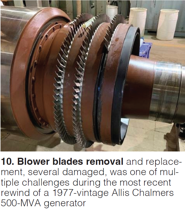
You’ll have to check out the slides to learn the challenges overcome during the rewind, subsequent overspeed test, and rotor rebalancing (Fig 10). Once the rotor appeared ready for service, vibration began to creep up three months into operation. One unique finding during the investigation: a snapped structural H-brace, apparently added two years after COD, with loose mounting bolts on the exciter outboard bearing which was found loose and unloaded in its spherical seat.
“Generator FME – importance and historical consequences” will make sure you don’t become complacent about foreign material exclusion (FME), or simply, stuff left inside a generator that doesn’t belong there. There’s a bit of humor in the slides involving lanyards for your safety glasses you won’t want to miss, if numerous examples of foreign objects found inside and their consequences aren’t enough. FME is responsible for major generator damage every few years and minor damage several times a year, the presenter notes.
How do you ensure FME from your unit? The last slide is the money shot, listing obvious but also obviously overlooked steps like accounting for all material taken into the workspace. and detailed inspection by experienced personnel before the access point is closed. Practically, you can: (1) create a barrier at open areas, (2) secure with FME tape or hard barrier with a log book for components taken in and out (depends on the honor system, though), and (3) a full-time gate attendant (not perfect but effective).
“TLRI Generator Rotor Failures” reviews two events – unit behavior and operator notices, findings and testing, and repairs – suffered at a site with this model generator. The first is a J-strap failure, the second a glycol cooler leak-related failure. Numerous photos accompany the narrative.
“GE 324 Generator Rewind Case Study” covers the challenges faced after a 263 MVA unit tripped on A phase differential running at 110 MW (unit rated at 197 MW). Subsequent O/O and OEM electrical tests were inconclusive. Three months before, the ST/G unit went through a three-month overhaul outage under an LTSA with the OEM at which time it passed all electrical tests but failed a bump test when the plant was looking into the modifications recommended under TIL2417 R1.
Management decided not to perform the mods for reasons listed in the slides, the most notable being a generator field replacement scheduled for 2027. You can guess what happened when the last slide recommends to the audience that they make the end winding modifications under 2417.
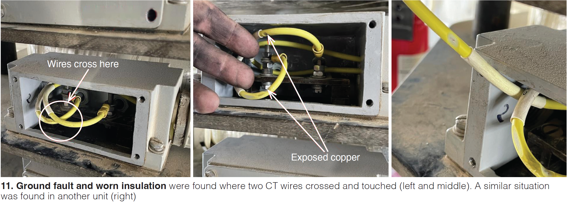
The other important recommendation is to check current transmitter wiring. This site found worn insulation and a ground fault where two wires crossed and were touching (Fig 11). Two similar instances of crossed CT wiring were found on other units.
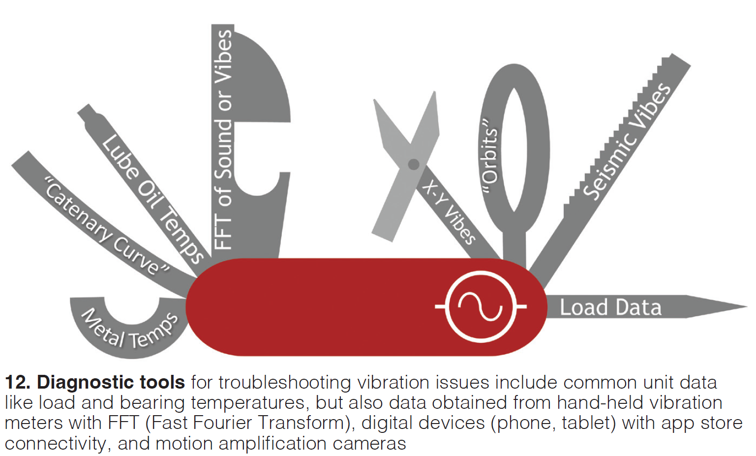
“Troubleshooting generator vibration” is about as concise a guide to the subject as you’re likely to find written for plant personnel (not vibration specialists) and available for free. The material presented is relevant for “about 75% of the vibration issues you’ll typically see.” This is a “must view” if you’re training a plant engineer or technician in vibration analysis.
One of the first slides is “know your tools.” A large table (vibration issues in rows, measured parameters and characteristics in columns) offers guidelines to link different issues with their common data patterns and determine what is commonly seen with that issue, and what is not (Fig 12).
GUG VENDOR PRESENTATIONS
“Generator Protection Theory,” Doug Weisz, Hubbell Power Systems/Beckwith Electric
Among the features of the 200+ slides supporting this four-hour training tutorial is a discussion of generator protection in the context of the NERC standards which were developed as a response to the US blackout of 2003, largest in North American history. These standards are intended to keep units online, if possible, without damaging equipment so they are available to support the system and prevent the blackout from spreading.
Otherwise, the list of topics in the table of contents alone is daunting unless you are an electrical engineer or a generator specialist. Perhaps more than anything, the presentation indicates the value one gets from the modest attendance fee for these parallel user group conferences.
“Demystifying Epoxy Resin Systems in Generator applications,” Chris Klein, Astro Chemical
Topics covered include epoxy chemistry review, overview of applications in large generators, and frequently asked questions which don’t necessarily have obvious answers. For example, under “can I use this resin for that application” is the advice not to mix epoxies and polyesters but also that every supplier has a “jack of all trades” product which can be used in multiple applications. Tying and saturating resins make for good adhesives and protective coatings.
“Generator Stator Condition Assessments and Decision Making,” Jamie Clark, AGT Services
Big headline from this presentation is that a huge number of stators are reaching the end of their design lives, there are more unplanned stator rewinds than ever, large O/Os are planning/budgeting fleetwide stator and field rewinds over the next five years, and the shop and field service resources to handle all this isn’t increasing.
The more specific headline items from this presentation are (1) bolted joint integrity (and failure of the brazed joints) is a “big issue” but can be detected with on-line monitoring, (2) all OEMs have bulletins out on end winding issues, (3) global core looseness can be a problem with newer GE units, (4) loss of core compression will lead to core winding faults, (5) OEM upgrades often ignore generator constraints or operating history, (6) every unit should have a flux probe installed and a flux probe evaluation should be conducted at least once a year, especially if you have changed operating profiles, (7) the OEM should do a borescope inspection under the retaining rings during a minor, and (7) it takes 4-6 months to get a new set of windings.
“Electromagnetic Interference Monitoring Case Studies,” Kent Smith, Cutsforth
To illustrate the value of EMI monitoring, plant components and situations under scrutiny here include generator hydrogen analyzers and water accumulation, circulating water pump motors, excitation power rectifier, loose wedges in water cooled generators, isophase bus, bearing electrolysis, isophase bus link, and turbine bearing.
“Generator Overheating Detection and Response with a GCM-X,” Christopher Breslin, Environment One
The GCM-X (generator core monitor) detects sub-micron particles emitted when epoxy paint and/or core laminating materials overheat and thermally decompose. Device should be a key component for monitoring your hydrogen (or air) coolant auxiliary equipment, especially because the fleet is aging, workers are younger with less training, periods between outages are extended, and units are heavily cycled. Slides review data trends in several case studies and ways to better understand your GCM system and how to maintain it.
Brushless Excitation, Parallel vs Series, Jacques Leger, WEG(EM)
Slides focus on redundant protection schemes found on generator rotating rectifier wheels with series or parallel diode arrangements, common failure modes, testing and troubleshooting, and AVR fault reaction and options for diode fault detection through the AVR.
“Exercising Your System (The Importance of Testing and Cycling Your Electrical System,” Nathaniel Smith, TEMs
Although NERC PRC-005 says cycle your electrical equipment, most plants only do this for the mandated items which interface with the bulk electric system. This presentation suggests that you cycle all your electrical systems every opportunity you get, including protection and lockout relays, AC sensing devices (current and pressure transmitters), and breakers. Maintenance recommendations are included.
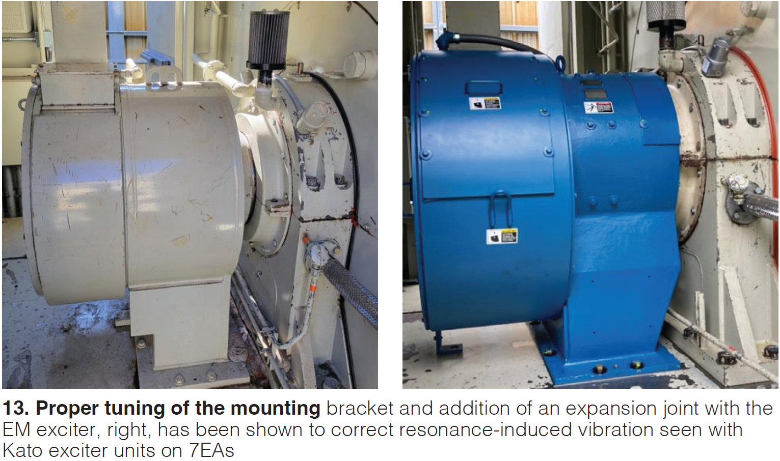
“Diagnosing and Correcting Exciter Cab Resonance,” Danny Besmer, WEG(EM)
Slides convey the lessons learned and troubleshooting methods while resolving vibration issues attributed to natural frequency resonance found on 7EA generators. In particular, design and mounting features of an EM exciter have been found to correct resonance induced vibration characteristic of Kato exciters in some projects (Fig 13).
“Safety Differently: A Story About How Your Organization Could Learn Differently,” Matt Barnes, MD&A
Message here is that team performance improves when you work through a safety event with positives instead of the absence of negatives. Positives include the capacity to be successful under varying conditions, the ethical responsibility to the organization which has to handle messy, risky work, and making sure the people perceived to be part of the problem (those involved in the safety mishap) become part of the solution.
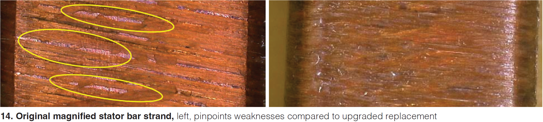
“324 Generator Failure Discoveries, Concerns, and Repair,” Howard Moudy, NEC
Subject of these slides is the investigation, discoveries, and repair of a failure resulting from a T2-T5 ground fault in a 321 KVA generator a few months after an outage that included a full stator rewedge and DC HiPot. Root cause proved to be compromised strand insulation of the top bar #63 which progressively shorted to adjacent strands, causing severe overheating and ground wall deterioration. The replacement strand features double serving crosshatched Dacron glass with no exposed conductor, unlike the original (Fig 14). Presenter recommends that upgraded insulation be part of future rewinds.
“Generator Field Issues Which May Extend Your Outage,” Jamie Clark, AGT Services
General categories covered are slot component migration, distance blocking movement, turn insulation migration, copper distortion, braze design/failure, collector systems, and H2 seal oil systems. Slides are replete with examples (and photos) of defects in both OEM and third-party rewind work.
“Damaged Main Lead Field Copper,” James Joyce, MD&A
After explaining and illustrating the purpose of the main leads, leaf vs solid plate designs, radial/rotational failures, and electrical failures, slides proceed through improved main lead design features and support modifications, along with several photos of the installation process.
“Stator End Winding Concerns with Newer Vintage Generators,” Howard Moudy, NEC
Since 2013, there have been at least 10 failures of phase straps in 324 model generators, and three TILs issued to try to mitigate the problem. The long-term solution is to coordinate all end winding components to eliminate the accumulation of stress which leads to deterioration and failure. Attention to end windings is critical to generator maintenance.
End winding movement from normal vibration levels should be addressed by inspection and monitoring, and repair if necessary. Movement from vibration due to resonance requires detuning and retesting. Movement from thermal contraction and expansion of the end winding itself (caused by unit cycling) is becoming more of a problem and requires more diligent monitoring and implementing long-term solutions, such as specialized engineering approaches offered by NEC.
“Two 2024 EPRI Projects,” Bill Moore, EPRI
Slides offer deep insight (though not definitive answers) to the questions (1) Do we rewind the generator now, later, or run to failure; and (2) is a global vacuum pressure impregnated (GVPI) generator a better investment than single bar VPI and resin-rich designs? Regarding (1), insight takes the form of visual observations (supported by photos) indicating a rewind is necessary now, testing results that suggest the same, and common reasons for stator and rotor rewinds based on an industry survey.
Results from surveys returned by fifteen utilities representing 500 GVPI units are included. While the design certainly has advantages, two areas of concern highlighted are that 64% of respondents report at least one in-service failure or developing failure mechanism, and GVPI stators are “notoriously difficult to rewind.” 27% of respondents would not choose a GVPI unit again in the near future.
Closing reminder. End users registered at www.powerusers.org are encouraged to download the full slide decks from the 2024 conference and put the shared experience and lessons learned to immediate use. The material spans everything from outage planning and controls upgrades to generator rewinds and cold-weather prep—practical, field-tested guidance that speaks directly to today’s plant challenges. And if you’re not already planning to attend the 2025 Combined Conference, set for August 25–28 in Washington DC, now’s the time. Few events offer as much actionable content, peer exchange, and expert access in one place.
More from the 2024 Combined Conference:
- Life-long learning abounds across five user group conferences @ Power Users Combined Conference
- Addressing weather resilience, risk management, and outage execution @ CCUG
- Focus on D11 strategies, EHC pitfalls, and skilled labor shortages @ STUG
- Generator users share failures, fixes, and forward planning @ GUG
- Advanced controls strategy and fundamentals @ PPCUG