


The 2021 conference of the Generator Users Group was a virtual event like the highly successful 2020 online meeting. This year’s conference, conducted under the Power Users umbrella, aired on consecutive Thursdays from July 15 through August 5, plus Wednesday, July 21—too late for technical coverage in this issue of CCJ.
Steering Committee Chairman Dave Fischli of Duke Energy opened the meeting on the 15th at 11 a.m. Eastern US, the starting time for each day of the conference. Sessions ran through 3:30 p.m. each day. Topics addressed in user and consultant presentations include axial migration of rotor coils, rotor failure after flux-probe test uncertainty, rotor tooth-top cracking, retaining-ring inspection and testing, radiographic inspection of phase straps, stator-winding collateral damage attributed to an isophase bus fault, EMSA mapping of a stator, fault inspection criteria for large current surges, and stator-winding resistance tests.
Presentations are available to registered owner/operators in the GUG area of the Power Users website at www.powerusers.org. Included are the PowerPoints from several of the leading vendors in the generator community—including Cutsforth, National Electric Coil, Magnetic Products and Services, Omicron Technologies, BPhase, and AGT Services.
If you have never attended a GUG event, the summaries of user and sponsor presentations from Weeks Three and Four of the 2020 virtual meeting in this issue of CCJ will speak to the value of participation in a future conference. Information shared at these forums, vital to your professional development and your plant’s success, is available only through Power Users.
Registered owner/operators also can access the user and consultant experiences and presentations made by third-party products/services providers during Week One of GUG2020 (November 12) on the Power Users website. For technical presentations made by the OEM during Week Two (November 19), visit GE’s MyDashboard website at https://mydashboard.gepower.com.
Weeks Three and Four
User and consultant presentations
Use of an ultrasonic device for locating hydrogen leaks
A handheld ultrasonic instrument commonly used for detecting vacuum and air leaks in powerplants is good for locating leaks of hydrogen and other gases as well, reported an experienced user.
The Fluke ii900 Industrial Acoustic Imager (a/k/a sonic leak detector) relies on an array of 64 digital mics to locate the source of the sound (Fig 1) within a frequency band of 2 to 52 kHz. Practically speaking, the instrument can detect a 0.005-cfm leak at 100 psig from up to 33 ft away. It doubles as a camera capable of capturing stills and video, and has a USB-C port for data transfer.
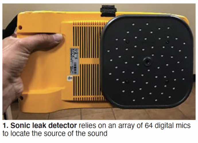
Fig 2 shows the acoustic signal developed by a small hydrogen leak from a generator bushing.
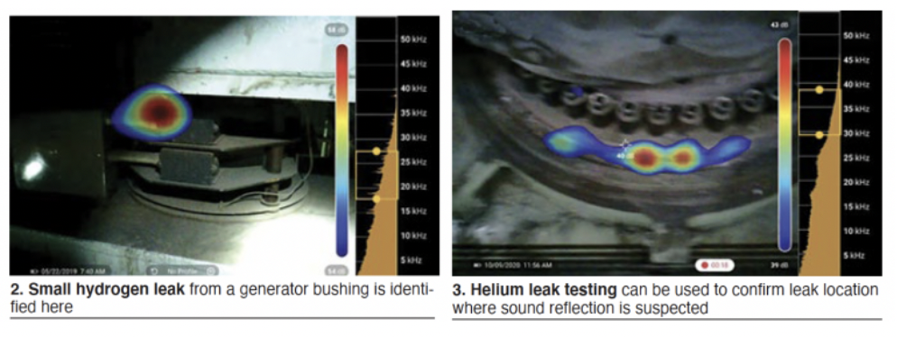
The speaker cautioned that sound can reflect off surrounding surfaces and could be misinterpreted as a leak in the wrong location. If a potential leak source is identified, he recommended viewing the same location from a different angle or distance to verify that the leak source is “true” and not a reflection. Fig 3 is an example of a leak indication caused by sound reflection. The false indication was verified with helium testing.
A thorough understanding of a turbine’s gas piping system and design benefits accuracy. The user added that the default frequency range and filter settings are acceptable for most compressed gas leaks but may require adjustment in noisy environments. This is a trial-and-error “tuning” process.
User safety—avoidance of slips, trips, and falls—was stressed. Surveyors should remain aware of their surroundings while walking and viewing the screen during scans, attendees were told.
Origins of EMI: History and New Research Users Group
The value of radio frequency (RF) for sensing incipient arcing faults in large generators is well known to electrical engineers serving in powerplants. However, questions remain on how to interpret the RF spectrum signature created by high-frequency currents flowing in the neutral connection. The speaker said there are many possible sources of RF signals—some are within the generator, some external to the generator.
In the first group are the following:
Partial discharges (corona) within the stator-winding insulation.
Slot discharges between coil surfaces and the stator iron.
Sparking from exciters with brushes.
Arcing between adjacent ends of a broken coil strand.
The second group includes the following sources:
Corona and partial discharges in the associated high-voltage power system.
Lightning and switching surges.
Motors, switches, and other sources in the power station.
Application of the RF arc-sensing technique is straightforward. To measure the complete spectrum, simply clamp an RF current transformer around a generator neutral. Radio noise meters covering the frequency range of interest—about 10 kHz to about 32 MHz—provide the measurements in microvolts quasipeak (µVQP). This is explained as sort of a weighted average approaching the true peak value of the frequency component being measured.
Numerous RF measurements from operating machines have resulted in recognizable RF spectrum signatures, generally repeatable and believed to represent the background levels of normally operating machines free of any arcing condition.
Note that preliminary measurements suggest that RF noise external to the generator (refer to short list above) is insignificant.
The speaker called for the formation of a new industry group—perhaps something like one of the users groups covered regularly by CCJ—to research EMI (electromagnetic interference) signature correlation to a given fault condition, develop tools to interpret the signature to fault conditions, and document and communicate the knowledge worldwide.
One of the tools at the disposal of the proposed research group is an electromagnetic transients analysis program, called ATP, developed by Bonneville Power Authority under a federal grant. The speaker said the program has a significant number of users sharing results globally.
GVPI stator-bar failure root cause, lessons learned
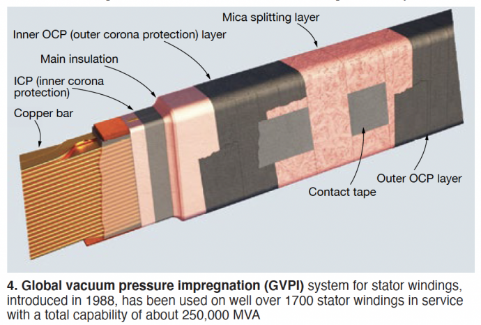
This is a well-illustrated presentation many O&M technicians can learn from. It addresses the failures of two different SGEN6-1000A generators serving gas turbines in a 4 × 1 combined cycle. The four units are characterized by globally vacuum pressure impregnated (GVPI) stator windings (Fig 4).
The first failure was on a 245-MVA, 15-kV machine after nine years of operation. An incorrect cable termination was used during plant construction. The spec called for unshielded cable, but 2/0 shielded cable was used and the shielding was not removed for the approximately 8 in. needed at termination. Because the shielding was not stripped back, it was within strike distance when the fault occurred. The current jumped into the shield rather than travel in the cable conductor, thereby overheating and failing the cable.
The second unit failed a stator-winding hi-pot after 10 years of operation. The test target was 33 kV, 2.2 times rated voltage, as it was for the first unit discussed above. In one phase a bar failed at 30 kV and in another phase a bar failed at 16 kV. Visual inspection showed an “insulation anomaly” on the top surface at core exit on both failed bars. Two other bars that had not failed also displayed the same insulation anomaly.
Several stator bars were extracted for root-cause analysis. A full rewind was performed on this stator. The slides did not comment on the difficulties of removing bars from a GVPI winding.
A CT scan on two failed bars showed signs of what appeared to be insulation cracking internal to the bar at the location of the ridges on both bars that failed the hi-pot, as well as the other two bars with ridges in the insulation. These flaws would be a very serious concern to the fleet of similar units, but the slides did not comment on this issue.
Nonmagnetic retaining ring in-service inspection drivers in 2020 and beyond
In-service inspection of generator retaining rings became an industry standard practice for plant owner/operators in North America and Europe during the mid-1980s, reminded Neil Kilpatrick, principal at GenMet LLC, a respected consultancy on generator metallurgical matters. Many 18Mn5Cr rings, the standard until that time, were found to exhibit significant stress corrosion cracking and most were replaced with 18Mn18Cr rings, which are not susceptible to SCC in water.
But the materials change does not mean you no longer have to perform periodic ring inspections, Kilpatrick said. You never know what might go wrong. He said the following are typical of the failure mechanisms which could cause concerns:
Fatigue fracture (start/stop).
Fault-related electrical damage to rings.
Fault-related friction damage to rings (rubbing).
Subsynchronous oscillation, with torsional fretting and fatigue cracking.
GE 7FH2 extreme vibration during LCI operation
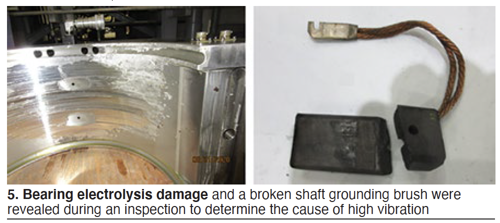
Generator vibration observed during a turbine start using a LCI (load-commutated inverter) was “impossibly” high, the speaker said, showing comprehensive data plots on two slides. Focus of the initial inspection was on bearings (wiped? debris in lube oil?), LCI function, and lift oil (working properly?). LCI was later dropped from the list because it was shared with a sister unit onsite with no issue. GE suggested the cause might be turn shorts, based on its review of the data.
The engineering inspection and evaluation team identified electrolysis at the bearing (Fig 5), significant wear of hydrogen seals, broken shaft grounding brush, and a highly magnetized rotor (upwards of 450 gauss). Bearing repaired, shaft demagnetized to the extent possible with the rotor in place, a restart of the heavily instrumented unit was attempted. Seismic probes revealed an “impossible” 306 ips at 600 rpm.
Flux-probe waveforms showed a coil-to-coil short, with all the turns in one coil and half the turns in another being bypassed. The practical solution given time constraints: a rotor swap. Photos of initial findings when the unit was opened revealed deformed pole-to-pole connectors. Important to this discussion was that the normal pole crossover for a 7FH2 machine was not used when the generator was rewound previously by an alternative OEM and the replacement failed at about 700 starts and 11,500 hours.
Shop work included replacement of the two affected coils using pole-to-pole connectors of the generator OEM’s design. Problem solved.
Conclusions and lessons learned included these:
Things can change completely from one start to another.
Confirmed that turn shorts can cause exceptionally high vibration during an LCI start.
Reinforced the need to inspect other units in the power generator’s flee with a similar pole-to-pole connector.
If it’s not broken, don’t try to fix it—referring to the change from the OEM’s hairpin pole-to-pole design which has worked well over the years.
SFRA study on generator stator re-wedging
The Sweep Frequency Response Analysis test generally is associated by plant personnel with the physical condition monitoring of transformer windings. It is an efficient way to detect displacement of the transformer core, deformation and displacement of the winding, faulty core grounds, collapse of partial winding, broken or loose clamp connections, shorted circuit turns, open winding conditions, etc.
In this presentation, the speaker presented three case histories and more than 50 slides to show the value of SFRA in determining when stator re-wedging is necessary. There’s still more work to do but the message is clear.
Wonder why wedge tightness is showing up in SFRA data? The speaker explained thusly:
A loose wedging system opens clearances.
Clearances permit movement of coils/bars to release installation/migration stresses.
Movement opens gaps and contact points affect capacitance and inductive coupling, and resistance to ground.
Things to keep in mind when trying to apply the SFRA data include the following:
Fresh paint affects readings; make sure all paint is cured before gathering data.
Meaningful data are limited.
The analysis presented is global in nature; local issues may not show.
Coil/bar displacement is a dependent variable.
The test cases presented are for hydrogen-cooled machines. In-slot partial discharge damage may affect readings for air-cooled generators.
The test cases also are for 2-pole machines. It’s unknown at this time if the same patterns apply to 4-pole and hydro units.
AeroPac brushless-exciter flashover
It’s 0800 and the subject unit is synchronized with the grid; power is increased to 110 MW within the hour. Load is raised to 140 MW and the unit trips at 0915 on a loss of generator exciter voltage. The operator’s screen reads, “AVR fault.” No obvious issues are identified and the operators decide to re-energize the unit figuring the trip was “false.” But the unit trips again before it can be synched.
Inspection with assistance from a third-party services provider identified dust on the excitation generator, which was difficult to access. Molten metal was found in the diode wheel; it took three shifts to remove. Decision was made to remove the complete excitation generator housing.
The rotor shaft was damaged during the incident (very deep gouge) so it was pulled and sent to a shop for inspection, analysis, and repair. Electrical test results with the rotor out were satisfactory. Another observation: All six diodes failed but investigators were not able to determine how many failed before the incident. An alarm indicating diode failure was never received. Diodes had never before failed on any of the company’s generators.
Repairs: The portion of the shaft with the deep gouge was removed and a new piece welded it its place. The excitation generator and diode wheel also were scrapped. Shop discovery: A socket head cap screw was found wedged in the diode wheel casing and the connection from the diode wheel to the radial lead was melted in half. Electrical tests received a passing grade; the AVR was eliminated as the root cause.
With the RCA still in progress at the time of the presentation, the plant took the following actions:
Planned to check the tightness of all bolts during every major outage.
Purchased a handheld device to monitor diode condition; data would be collected monthly.
Initiated work with the OEM on changing the type of filters for the air-cooled excitation generator.
Planned to clean the excitation generator every four years and to replace the diodes and their hardware every 10 to 12 years.
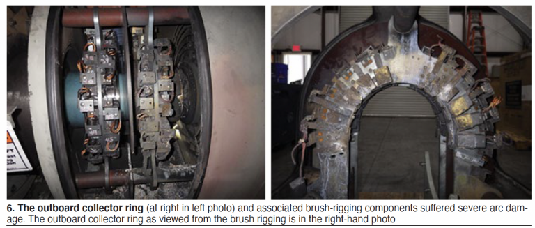
7FH2 collector flashover event
This presentation affords the rare opportunity to experience a collector flashover event, which lasted less than an hour, virtually. The generator damaged was a 239-MVA, 18-kV, hydrogen-cooled machine. Data, details in words, graphs of operating data, a dozen photos, etc, are provided.
The outboard collector ring and associated brush-rigging components suffered severe arc damage (Fig 6 left, outboard collector ring is at right in the photo): eight brushes detached completely, seven still attached by their pigtails were free of their holders, nine brushes remained stuck in their holders—attesting to the level of detail provided by the speaker. All 24 brush holders showed arc damage (Fig 6 right).
Repair scope included replacement of the following components:
Entire brush rigging, including new holders and brushes.
Both collector rings (the inboard ring could have been reused, however).
Outboard collector terminal stud (the existing one had to be drilled out).
Seal assemblies on both terminal studs.
Plus, shaft grinding was required to remove harden metal created by arcing.
Identification of the exact root cause of this flashover event was complicated because most of the evidence was vaporized during the incident. Insights gained during the inspection allowed elimination of the following possible causes as unlikely: short brushes, high brush vibration levels, inadequate ventilation, and ambient air contamination.
Among the contributors to this specific collector flashover were believed to be generally low current densities in the brushes, ineffective periodic cleaning of brush holders by contract personnel, poor contact between brush terminals (pigtails) and the outboard collector yoke assembly, and improper orientation of brush holders relative to the collector ring. In brief, the speaker believed the brush holders had outlived their useful lives.
The speaker offered the following characteristics of good collector assembly performance:
Continuous contact of brush to collector ring.
Proper brush-to-collector ring contact pressure.
Good collector-ring surface film condition.
Limited selectivity.
A proven maintenance approach to assure good collector assembly performance focuses on these points:
Routine checks of collector assemblies with rounds on each shift.
Weekly checks with the enclosure covers removed—including visual inspection, verification of no abnormal brush vibration, and confirmation of brush freedom of movement within the holders.
Monthly, measure brush currents. Compare these to those from the preceding month to identify any obvious current selectivity.
Identify and log specific deficiencies, if any, identified with the prescribed maintenance approach.
GUG steering committee for 2021
Chairman: Dave Fischli, Duke Energy
Vice chair: Jeff Phelps, Southern Company
Jane Hutt, International Generator Technical Community
Joe Riebau, Exelon
Craig Spencer, Calpine
Kent Smith, Duke Energy
Jagadeesh Srirama, NV Energy
Founding members of GUG who recently retired from the committee are John Demcko of EUMAC Inc and Ryan Harrison of Heartland Generation Ltd (Canada).
The idea for a generator users group, and the energy behind its launch came from Clyde V Maughan, president, Maughan Generator Consultants, Schenectady, NY. Maughan retired from active participation in the organization a couple of years ago. He turned 95 early this month.
Special technical presentations
Presentations made by National Electric Coil, MD&A, AGT Services, and Siemens Energy to owner/operators participating in Weeks Three and Four of the virtual GUG2020 conference are summarized below. You can access the PowerPoints submitted by the first three vendors on the Power Users website at www.powerusers.org. The Siemens presentations are posted on the company’s Customer Extranet Portal (CEP). For help in locating them, contact your plant’s service representative.
Corona in HV stator coils: Theory, causes, repair, laboratory prognosis
W Howard Moudy, director of operations for National Electric Coil, is a frequent presenter at user group meetings. His goal here was to help plant personnel better understand what corona is, the damage it does, how to identify its presence, and the need to repair the damage it causes early, to avoid the possible need for a coil replacement.
But first, a brief backgrounder on the terminology, extracted from an article written for CCJ by Donald Selkirk, PE, of SaskPower several years ago. The terms corona and partial discharge (PD) are commonly used interchangeably in the electric power industry, he wrote. However, this is not correct.
Both corona and PD are electrical discharges that occur in high-voltage rotating machines (HVRM) when the strength of the applied electric field is great enough to cause ionization.
The IEEE Standards define corona as a “luminous discharge due to ionization of the air surrounding a conductor caused by a voltage gradient exceeding a certain critical value.”
PD is not necessarily luminous or visible. Further, PD may not occur adjacent to an energized conductor and need not occur in air or gas. Additionally, a corona discharge may bridge the entire gap between energized conductors.
Moudy continued: Corona is a surface phenomenon (a “glow”), he said, that leaves its distinguishable mark on winding surfaces, both in the cell and end-winding portions of HVRMs. It is often caused by insufficient clearances between surfaces having different electrical potentials.
Corona also may be attributed to inadequate functioning of the gradient portion of the outer corona protection (OCP) wrap encapsulating stator bars (Fig 7). Erosion of the OCP, he continued, can develop from inside the coil when the ground-wall insulation near the OCP is of poor quality. Mica is a material that may best inhibit corona attack on ground-wall insulation.
The insulation binder is attacked first, followed by the conductive fillers of the OCP material, which may be destroyed. This allows the corona to reach the OCP surface, where it is easy to recognize (Fig 8). Moudy noted that OCP repairs made prior to deterioration deep into the ground-wall insulation are most successful. Given reasonable access, he said, future deterioration in the area of repair can be prevented. Then the prognosis for long-term reliability is very good.
HV generator stator ground insulation repairs
This presentation by National Electric Coil’s W Howard Moudy, director operations, and Gary Slovisky, director of field service, discusses in meaningful detail two case histories—one concerned with the repair of ground-wall insulation, the other with OCP (outer corona protection) repair. The second is a sequel to Moudy’s first presentation (immediately above).
Before committing to a repair, the speakers began, there are things you should know—including the following:
Understand the cause of the failure.
Determine the full extent of damage and the suitability of undamaged components.
Identify the repair options.
Consider the practicality of the repair options identified and their associated risks, and the prognosis in terms of reliability.
Participation and guidance by experienced personnel with a bit of wisdom is essential for a successful outcome, Moudy and Slovisky said. Keep in mind that access and space often are the greatest obstacles in making repairs in the field. Creativity, patience, and experience are essential to overcoming these obstacles.
The root cause of damage to ground-wall insulation in the first case history was a rotor fan blade failure attributed to high-cycle fatigue. One of the 16 fan blades failed near its base but not at the weld joint. The liberated fan tip ring damaged the stator. The generator was relatively small, rated just under 22 MVA. The incident was characterized as a generic OEM design problem. The replacement 13-blade fan was machined from one block of ASTM 4340 alloy steel (no fan tip ring).
Interestingly, some owner/operators of air-cooled condensers equipped with fans having an even number of blades, identified with this problem. Their issues were resolved as well by transitioning to a fan with an odd number of blades.
These three repair options were considered:
Repair failed and damaged coils in-situ and onsite. This offered the shortest delivery time and lowest price, but the lowest evaluated reliability.
Factory repair and reinsulate the two failed coils; repair other damaged coils onsite. This option was penalized by a slightly longer delivery time than repair and about twice the cost of repair. However, it was less than one-third the rewind cost and offered a good evaluated reliability.
A complete stator rewind was characterized by longest delivery time, highest price, and highest evaluated reliability.
The first option was selected. Presentation illustrates how the ground-wall insulation was repaired successfully, step by step.
The second case history reviews OCP field repairs to a pumped-storage hydro generator and to a generator for an F-class gas turbine. Critical to achieving a successful OCP repair are the following:
Expertise and skilled labor.
Use of materials of the highest quality and of proven engineered processes.
Assuring an appropriate interface with the ground plane (core).
Thorough mixing of semi-conductive and gradient coating treatment materials.
Application of the gradient coating in a manner to assure proper/adequate overlap with semi-con coating.
Ensure adequate cure time.
Preparing generator rotors for cyclic duty
James Joyce, manager of generator repair operations at MD&A, set the scene with his opening statement: “The impact of cyclic operation on ac generators is significant. As more units transition from baseload to cyclic duty, the thinking behind generator maintenance and repairs needs to adapt.”
Keep in mind that baseload units operate under creep conditions—that is, constant stress—while cyclic units are challenged by the fluctuating stresses consistent with fatigue conditions.
Major contributors to increased wear on generator rotors in cyclic service, he continued, are these:
Different rates of expansion and contraction of rotor components in close proximity to each other that are made from different materials. Examples include copper coils, insulation, and steel forging (Figs 3 and 4).
Expansion and contraction of the retaining rings caused by centrifugal force.
Recall that heating of the rotor winding generally is the limiting feature in generator design. Thus, generators cooled by hydrogen, a more-efficient coolant than air, and are smaller than air-cooled units of similar output and issues related to the expansion and contraction of components are not as severe.
Important to note, Joyce said, that generator manufacturers are under increasing pressure to reduce costs and necessary decisions on conductor cross section, insulation thickness, the amount of steel in the core, etc, negatively impact a generator’s ability to absorb the increased mechanical and electrical stresses of cyclic duty. This puts pressure on O&M personnel to operate their machines within limits suggested by designers to assure the desired levels of reliability and availability can be achieved.
Joyce’s presentation focused on case histories illustrating the effects of cycle duty on the generator fields for a 450-MW hydrogen-cooled unit, a 200-MW hydrogen-cooled unit, a 300-MW air-cooled unit, and an 80-MW air-cooled unit. You can learn a great deal from the PowerPoint because the speaker shares the planned work scope for the shop visit, what was found during the inspection, emergent work required, solutions selected, etc.
Highlights include the following:
Cracked blocking required replacement with an enhanced design to prevent crushing and delamination.
Replacement of original Nomex turn insulation with a glass laminate material which does not absorb moisture to the extent that Nomex does.
Modification of a full-length slot amortisseur, springs, and creepage blocks to accept a top hat pin which locks all three components together, thereby preventing the springs under the slot amortisseurs from migrating during operation.
Replacement of original slot armor with Teflon-coated Nomex. Note that the relative movement of the copper coils during load cycling can lead to abrasive damage to the slot armor. The Teflon coating provides a slip plane to mitigate this.
The original pole-to-pole connectors were susceptible to low-cycle fatigue as the copper coils expanded and contracted during cyclic operation. They were replaced with an improved design more capable of handling the additional stresses associated with cyclic duty.
Copper deformation from cycling dictated coil replacement. Plus, there were broken main leads not normally seen in situations involving high cycles; they too were replaced. New retaining-ring insulation also was installed, the replacement with a Teflon slip plane to prevent the end-winding top turns from deforming while expanding and contracting axially as they heat up and cool down.
Generator findings and case studies
James Joyce’s second presentation provides valuable information for all involved in generator-maintenance decision-making. You’ve heard at user-group meetings about outage extensions to deal with emergent work and may be wondering just how often such incidents occur. Joyce shares MD&A’s experience from the 18 months preceding his presentation Dec 3, 2020 to illustrate how important it is for you to operate your generator within the bounds of the OEM’s recommended practice, review operating data with a keen eye, conduct appropriate tests periodically, and to continually plan for the outage ahead—all this to minimize the number of surprises at the next overhaul.
The manager of generator repair operations said that most fields that come into MD&A’s shop fall into two categories: rewind, or rings-off inspection with a defined scope that does not involve a rewind—such as blocking mods, deep cleaning, or simple testing and inspection.
In the last 18 months, he said, 70% of the units that came into the shop were scheduled ahead of time. The rest were the result of a forced outage. In that latter group, about 12% participated in a field-swap program to minimize outage time. Roughly one-quarter of the scheduled visits required an outage extension because of emergent work (expansion of the original work scope).
Analyzing the root causes of field rewinds, Joyce said 46% of the generators had to be rewound because of a shorted turn or ground fault, 38% because of a main lead or mechanical failure (the latter category includes failed blocking, copper mushrooming, etc), and 12% because of contamination (such as foreign material blocking ventilation passages) that could not be removed. The remaining rewinds were age related.
Joyce concluded his presentation with two case studies, one involving a collector-ring failure, the other damage attributed to loss of lube oil. The first resulted from a flashover between the brush rigging and field forging. Once the flashover occurred the collector-ring insulation was compromised, allowing a ground fault from the collector rings to the field forging. Many photos illustrate the extensive damage incurred.
The field winding was unaffected by the flashover. This allowed removal of the damaged section at the end of the rotor and installation of a stub-shaft in its place. Machining of the turbine end journal and oil-deflector surfaces was part of the rework required. Successful inspections and high-speed balance confirmed the field was fit for duty.
The lube-oil failure experienced during startup after a maintenance outage did considerable damage. It occurred because the lube oil to the generator bearings was inadvertently shut off. The incident screamed for attention to detail on the deck plates, the use of checklists, and multiple pairs of eyes on everything.
The resulting bearing failure caused the shaft to drop about 200 mils. The rotating blower hub blades then contacted the stationary housing and shredded, sending the stainless-steel blades throughout the unit. Repair work included machining and weld restoration of journal and seal areas to eliminate hardness, installation of a stub shaft, a rewind and replacement of all insulation components, and blower replacement.
GE GT- and ST-driven generator field repair needs
AGT Services’ Jamie Clark has been on a mission for the last couple of years, presenting at the annual meetings of all major users groups to alert owner/operators about the significant increase in generator failures his company and other service firms are seeing. Clark’s thoughts echoed those of MD&A’s James Joyce in his presentation a week earlier, “Generator findings and case studies” (see above).
Both Clark and Joyce share the view that the failures experienced today are related in large part to unit cycling (in particular, those machines designed for baseload service) and age, with lapses in attention to detail during inspection and maintenance contributing.
Clark began his presentation with a chart illustrating the dramatic increase in the number of starts experienced by a combined-cycle plant in Maine over the last decade compared to the start stats for the facility’s first eight years of service. An informal survey that he conducted at a recent meeting revealed a 50% increase in the number of starts among 7F owner/operators. That was an interesting factoid because about half of “planned” projects that AGT Services has been involved in lately have resulted in emergent work. Another 14% of the surveyed users said their starts had doubled, or more than doubled, over the last 10 years.
AGT is seeing more unplanned stator rewinds than ever, Clark continued. Same is true for field rewinds, he added, with some of those resulting from stator failures.
Clark then highlighted the primary areas of the stator affected by cycling, including the following:
End-winding vibration/loosening, noting the higher risk for strand-to-strand series connections.
Core-looseness impacts—such as keybar rattle/belly bands and loss of core compression.
Slot support system—including wedge system and side packing/ripple springs.
The speaker stressed that all stator parts are designed to work together as a system. Example: Bellybands restrain keybars and when loose allow keybars to “rattle” producing particles of iron oxide. Add in some oil and you have greasing that lubricates the connections, further compromising tightness.
Clark’s extensively illustrated presentation next walks you through the primary field components affected by age/cycling (or design), focusing primarily on GE 7FH2 and 324 generators. Below is a list of the topics he covers. One or more has to be of sufficient interest to warrant a review of slides on the Power Users website.
Slot component migration
- Creepage block
- Amortisseur springs
- Slot armor deterioration (birth or prior repair defects)
- Turn insulation
Distance blocking movement
- Axial blocks
- Radial blocks
End turn insulation migration
Copper distortion
- Main leads, crossovers
- Elongation/foreshortening
- Fat copper in the slots
Braze design/failure
Cracked brazes at corners and on crossovers and leads
Collector systems
- Leaking stud seals
- Collector ring/brush life
- Field ground detector inoperative
Case studies: Cycling impacts on generators
Alejandro Felix, manager of generator service engineering, focuses in large part on the effects of flexible operation on stator end windings and then discusses the OEM’s innovative technologies to address flex-operation needs. For rotor components these include new designs for J straps and pole crossovers. For the stator, new rewind designs are more capable of absorbing axial thermal expansion of the coils. The presentation concludes with a look at Siemens’ service solutions to support flex operation.
Third-harmonic stator ground protection
Tony Cararano, solutions engineer, digs into the details of third-harmonic voltage and how to assure 100% stator ground protection not assured by adhering to IEEE standards. Readers may recall that Consultant Clyde V Maughan sounded the alarm on this oversight in the standards in the pages of CCJ several years ago (2Q/2013) after it had cost the industry hundreds of millions of dollars. Topics discussed include 59N neutral over-voltage, 27TN third-harmonic neutral under-voltage, and 64S subharmonic voltage injection. Three case studies provide valuable insights.
Hi-pot testing approach
Jim Lau, expert engineer and one of the industry’s most highly regarded electrical engineers, provided a backgrounder on high-voltage testing, covering both ac and dc tests. Dielectric evaluation, preparations to test insulation resistance and polarization index, the value of pass/fail dc hi-pot testing, partial-discharge testing, low-voltage power-factor testing are among the topics reviewed.