LEGACY CONTROLS FORUM, NO. 6 IN A SERIES
By Luke Williams, PE, consultant
www.geLegacyGasTurbineSupport.com
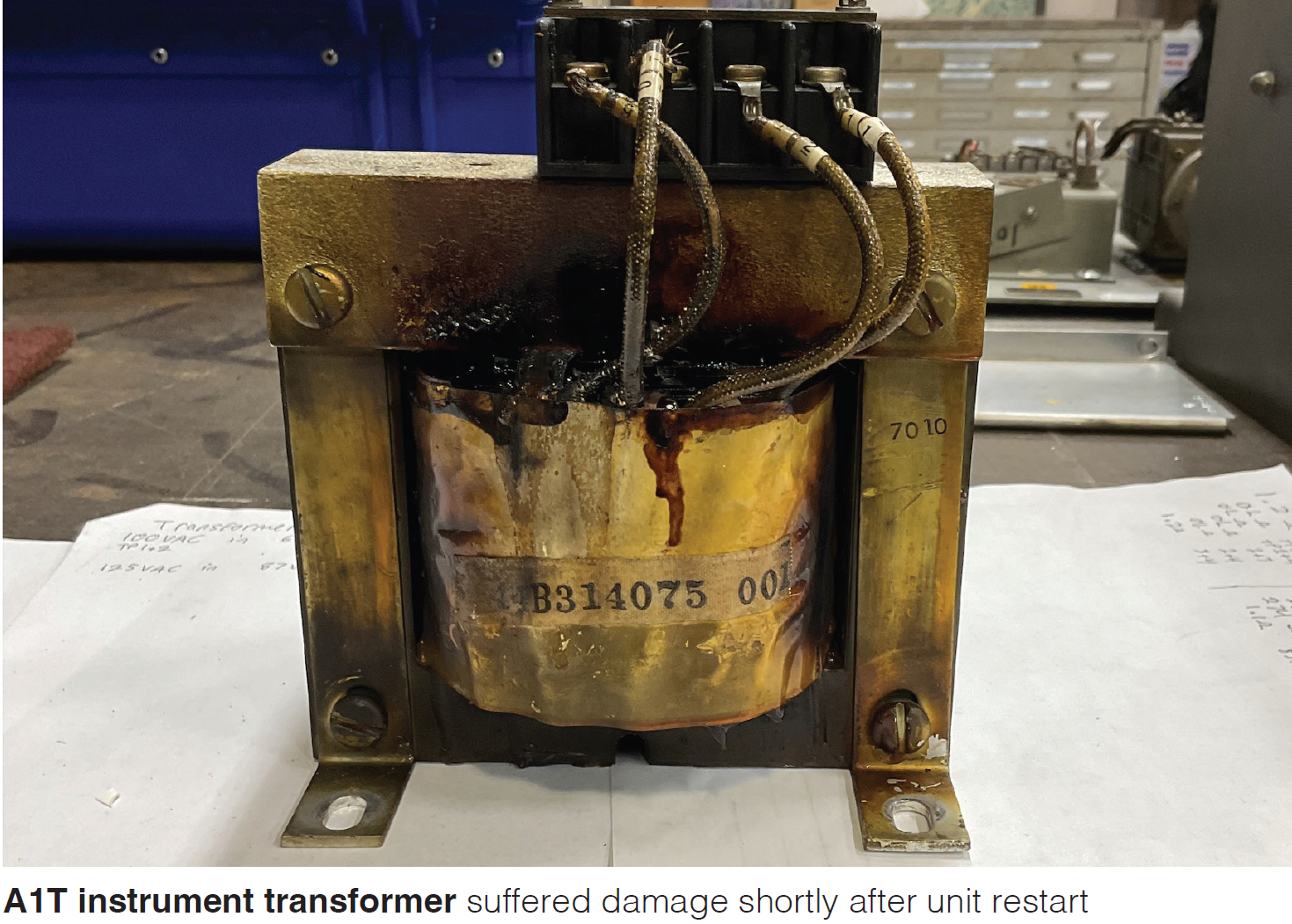
An MS7001B gas turbine with Mark I Speedtronic™ controls and SCR static exciter-regulator experienced overcurrent damage to its exciter on a normal startup. Operators think the overexcitation event lasted for several minutes. However, an overexcitation alarm was not received and the unit was tripped when personnel smelled smoke. Staff opened the generator panel and found the instrument transformer, A1T, on fire. There were no other alarms or flags. Although the operators are not sure, they think the field voltage was over 120 Vdc and the current over 280 A when the unit was shut down.
Some of the rectifier-bridge diodes were damaged and replaced, as were some of the control diodes in the control-panel rack. Two rheostats showed distress, including A6P, which was replaced. There also was damage to the excitation J15 plug and wiring, which were completely replaced. Nameplate information: Regulator panel, 3579315A224A1; elementary, 44D209431.
Instruction book is GEK-14772.
The point-to-point wiring, generator field components, online and offline resistors, 70R4 circuit, and the online control diodes and transformers were checked for shorts and grounds. The total resistance across the 70R4 was 1K and the resistance across the SCT (saturable current transformer) control winding and 90R5 was 25 ohms. No shorts or grounds, or open circuits, were found.
The unit was restarted, the field flashed at 40% of the turbine speed setpoint (TNH), and voltage built up slowly. At about 65% speed, field amps started rising rapidly; the unit was tripped at 260 A. Generator voltage was 11 kV and field voltage 108 Vdc. Investigators found the A1T instrument transformer damaged (photo). No other apparent damage was done to components or wiring.
Conclusion: Corrective action taken has not resolved the problem.
The A1T instrument transformer is across phases 2 and 3 of the PPT. Since the voltages on phase 2 and phase 3 normally are the same, the instrument transformer reduces the PPT voltage to a lower control voltage. No current flows since the phases are at the same potential. It appeared that the problem might have been a fault in the phase 2 and/or phase 3 PPT, SCT secondary, or linear reactor which causes a difference in the phase voltages and current.
The components of the excitation system—SCT, PPT, linear reactors, rectifier bridge, and field resistance—were tested and in operating condition. No faults were found. One resistor in the offline manual circuit, C6R, was found damaged and replaced.
The manual-to-automatic transfer relay, 83SR, was disabled to allow the manual regulator to check the offline and online voltages. The unit was started. At 40% TNH the field was flashed and the generator voltage started to increase. At full speed no load (FSNL), the generator voltage was 5 kV. The offline rheostat 90R5 was reduced to minimum resistance, but the voltage would not go below 15 kV.
Operators shut down the unit and adjusted the offline resistor C6R to increase resistance. Note that this is the resistor that had been replaced. Personnel started the unit and were able to adjust the FSNL offline voltage to 13.8 kV. Next steps were to close the breaker and adjust the online voltage to 13.0 kV.
Then the unit was shut down and the manual-to-automatic relay 83SR enabled. Restarted the unit, the field flashed, and the generator voltage increased. At 95% speed, control was shifted from manual to automatic. Generator voltage was about 12 kV and rising very slowly. At FSNL, offline rheostat 90R1 was adjusted, but had no effect. Also, 90R4 did not change the voltage.
The breaker was closed and negative-5 MVRS generated. The load was increased to see if the automatic regulator would control. VARS increased, but the generator voltage did not increase with load. The unit tripped at 20 MW with the field ground, generator differential, and loss-of-field protective relay flagged.
Operators meggered the field, finding high resistance. This would indicate that the generator differential and field-ground relay was a result of the trip—not the cause.
To eliminate the automatic regulator circuits, the 83SR relay was disabled and the unit restarted. The machine was ramped to base load—about 40 MW. Generator voltage remained at less than 13.8 kV and the VARS were 20.6. Conclusion: The manual regulator was working properly. The problem appeared to be with the automatic regulator.
The unit was shut down yet again and staff started checking the components of the auto-regulator panel. Finding: Resistor A7R in the A1CD gated diode circuit, 22,700 ohms, open circuit; replaced it.
Following the recommendation in the GEK troubleshooting guide for low armature voltage, personnel replaced the A1Z Zener diode, the A1CD gated diode, and the A2CD gated diode. Restarted the unit again with no improvement.
Next, replaced the saturable reactors A1SX and A2SX in the 90R4 input. Success! Upon unit restart, the automatic regulator was able to control generator voltage.
Conclusion: Test of the GAC devices—SCT, PPT, and linear reactors—indicated no faults. A reasonable root cause is that one or more of the connections on the SCT, PPT, and linear reactors introduced resistance which created a voltage and current differential between phases 2 and 3. Result was a significant overvoltage and overcurrent in the field wiring and control components. This problem was corrected when the components were isolated for test and reconnected.
An increase in resistance for one linear reactor would cause a voltage drop across it, resulting in a decrease in field voltage in the SCR of that phase. The other two phases then would attempt to increase the field voltage, resulting in overvoltage and overcurrent.
The exciter PPT, SCT, linear reactors, and diodes normally are located in the unit GAC in an enclosed cabinet. In this particular installation, the devices were mounted in an enclosure which was not weatherproof. Over the years, protective screens, weather strips, doors, and walls had allowed weather to affect the devices in the enclosure.
Bear in mind that maintenance on the generator and exciter high-voltage terminations should be done during the 50,000-hr outage or every six years—including inspection and upgrade of terminations showing signs of the effects of ambient conditions.
Two incidents have been reported recently on MS6001B engines shipped in 1996:
First: The affected site experienced damage to the GAC enclosure, including the access doors being blown off. Fault was a phase-to-ground short on the GAC PPT caused by rainwater entering the GAC from rust damage to the roof during a particularly heavy thunderstorm.
Second: This incident involved a series of trips and alarms, including: generator differential, DCS trip, TCEA PTR relay trip, operator selected excitation off, loss-of-excitation transfer to manual regulator, and excessive volts per hertz.
At one point the EX2000 remained at A5 and would not reset. Investigators found a rusted panel in the GAC compartment that allowed water to enter the cabinet in the area of the excitation control system. Although the EX2000 was not wet, there was standing water on the floor nearby. The high humidity level affected system electronics. The leak was repaired and the GAC dried out. Then the EX2000 was initialized and came back online.
As in the case of the first GAC excitation failure, bear in mind that enclosure age requires additional consideration when there is deterioration to the integrity of the compartment.
End notes: GE introduced the SCR static exciter-regulator in 1969. The Potential Source Excitation System followed in 1983. It featured ac and dc regulator control and added overvoltage and overcurrent protection. Some applications used linear reactors, which may have been involved with the static exciter-regulator failure.
Because more than a thousand MS5001, MS6001, and MS7001 gas turbines were shipped from January 1969 to December 1982, when the SCR static exciter-regulator was a standard component, the possibility of a similar failure exists on these turbines.
Finally, the earlier recommendation for scheduled maintenance on exciter HV components should apply to units shipped from 1969 to 1983 and is a good idea for any gas-turbine installation. CCJ