

Hill Top Energy Center
Owned by Ardian Infrastructure, Ares Management Corp, and Menora Mivtachim
Operated by NAES Corp
620 MW, gas-fired (with ultra-low diesel backup) 1 × 1 7HA.02-powered single-shaft combined cycle with a GE steam turbine/generator and heat-recovery steam generator, located in Cumberland Twp, Greene County, Pa
Plant manager: Pete Margliotti
Attemperator freeze protection
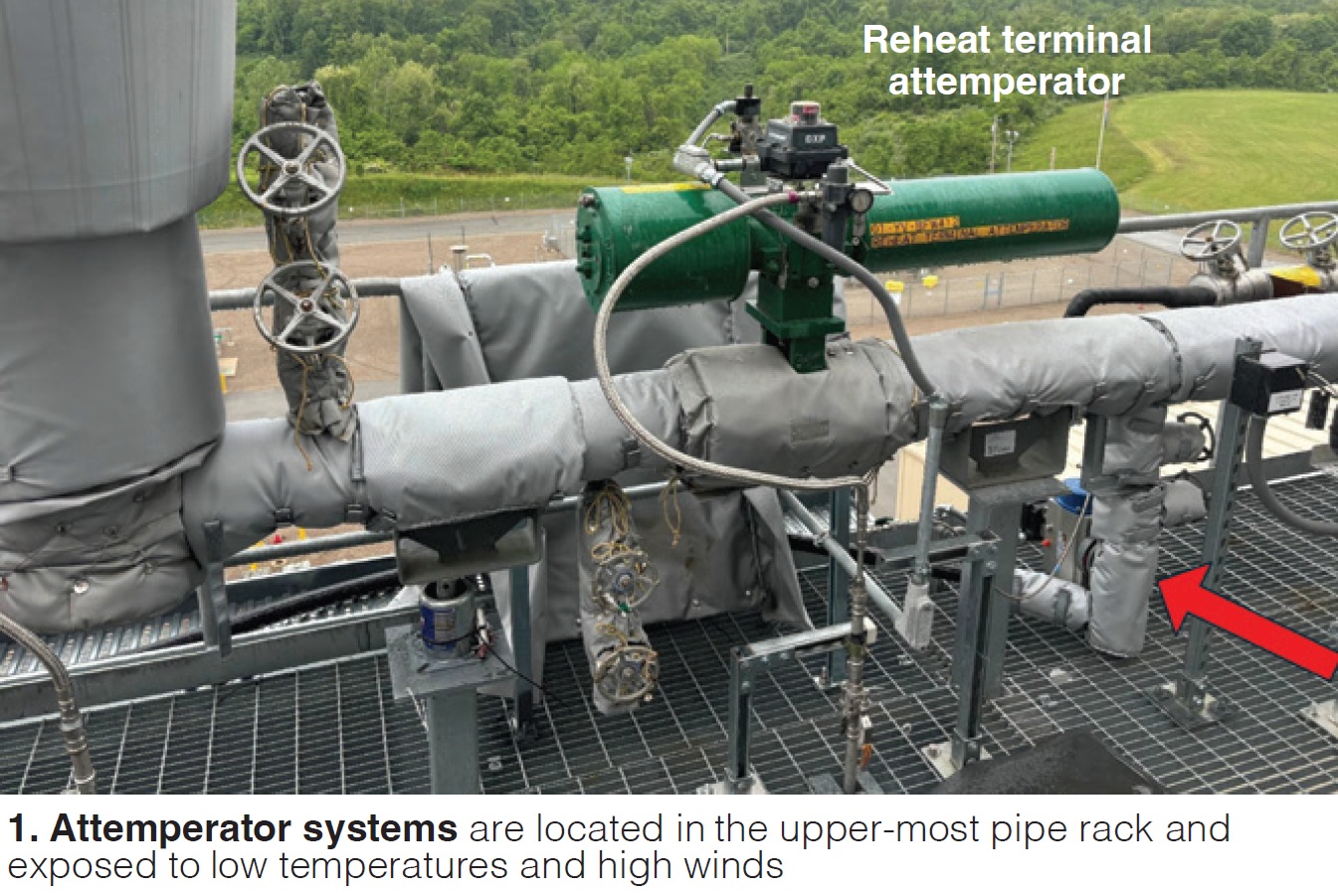
Challenge. The three attemperator systems serving Hill Top Energy Center’s heat-recovery steam generators are located in the plant’s upper-most pipe rack and exposed to extreme weather conditions—including high winds and low temperatures (Fig 1). Although the boiler feedwater supply lines that provide attemperator spray water to these bypass systems are heat-traced and insulated, staff elected to add a secondary means of freeze protection by addition of continuous-flow/leak-off lines upstream of the attemperator control and block valves (Fig 2).
These valves are located at the furthermost downstream ends of their respective pipe runs, thereby allowing water in the lines to lay stagnant when the station is online and in normal operation.
Stagnant water, plus the possibility of power loss to the heat-trace system, created additional concern for freeze potential when the unit is operating. The attemperators are required during a unit trip/shutdown; thus, if the lines freeze up it is not possible to attemperate steam flows bypassed directly to the condenser in a startup or shutdown scenario.
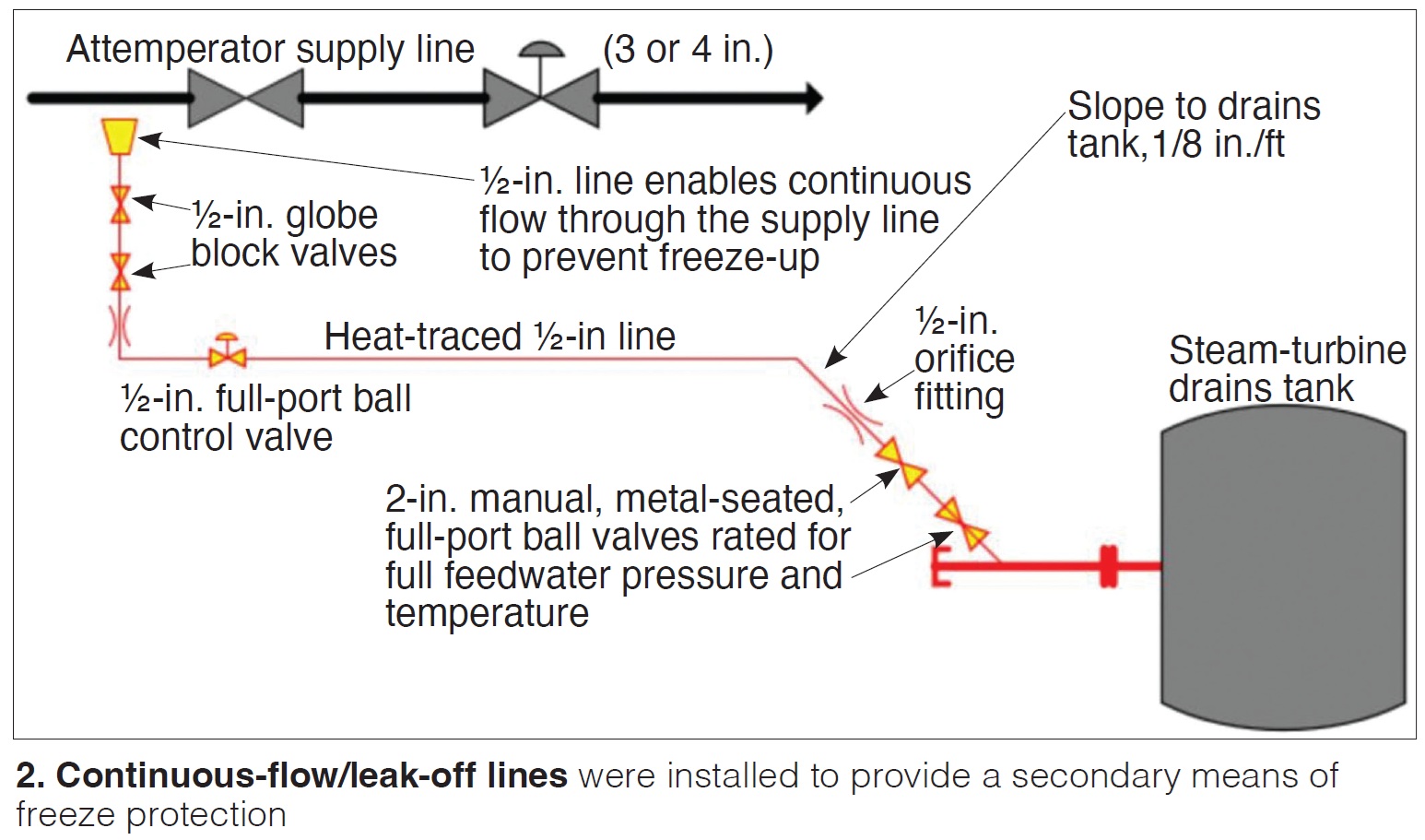
Solution. The attemperator lines, supplied by the boiler-feed pumps, are 3 or 4 in. in diameter, depending on the application. Continuous flow through the attemperator lines was made possible by installing ½-in. Weldolets in the attemperator supply lines (Fig 3) to provide a slip stream of 1-2 gpm of boiler feedwater to circulate through the supply lines. Flow control is by two ½-in. globe block valves and one ½-in. full-port control valve.
In normal operation, the two block valves are aligned in the open position and the control valve is shut until ambient temperature is below freezing for a period. At that time, the DCS signals the control valve to open and allow flow.
Immediately downstream of the control valve, each ½-in. heat-traced leak-off line is equipped with an orifice. Its size is based on the boiler-feed water pressure at the location. The nominal 200-ft-long leak-off lines route their respective slip streams to the turbine drains tank where they are collected for return to the condenser.
Additionally, ahead of the steam-turbine drains tank, a second orifice was installed and sized to apply proper backpressure to ensure the leak-off water does not flash to steam in the ½-in. line on their way to the drains tank.
Important to note is that just ahead of the orifice, pipe size and material were changed to 2-in.-diam P22 to allow for a flash area prior to gravity draining to the tank (Fig 4). Lastly, double-block 2-in. globe valves were installed in the flash area to enable drain-line isolation for future maintenance.
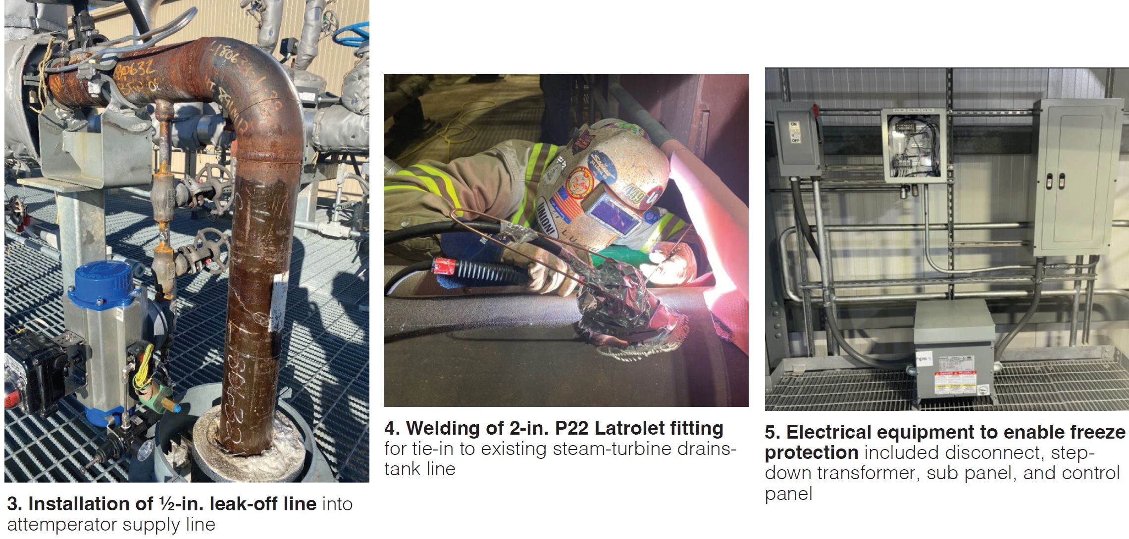
Note, too, that the ½-in. drain lines are supported by a cable tray sloped 1/8-in./ft in the direction of the tank. Also installed: A 480-V stepdown transformer and power panel equipped with individual isolation breakers (Fig 5). An RTD was placed near the pipe rack to provide a signal for on/off activation of the heat-trace systems serving the drain lines. Power indicating lights were installed at the ends of the drain lines to facilitate monitoring.
Results. The system has performed as intended; there have been no freeze-up issues.
Project participant:
Jon Mongold, maintenance manager
Comparing compressor-wash rinse conductivities for competing soap products
Challenge. Selecting the most effective soap for cleaning Hill Top’s 7HA gas-turbine compressor.
Solution. Maintaining gas-turbine compressor performance at a high level is essential for achieving acceptable combined-cycle output and efficiency. Reliable performance of the compressor water wash system is especially important in this regard. Central to the effectiveness of a water wash is the type of soap used, which should be in accordance with the OEM’s guidelines—such as quantity, flow rate, and other variables.
Factors to consider when selecting a soap include gas-turbine power recovery and rinse times and cost. After careful consideration of the biodegradable properties and feedback from other end users, the plant selected Rochem’s FyreWash F2 product.
Results. Top Hill Energy Centre found that switching to FyreWash had a positive impact on its operation. Comparison of rinse conductivity versus time for the two products compared are presented in Figs 6 (before) and 7 (after).
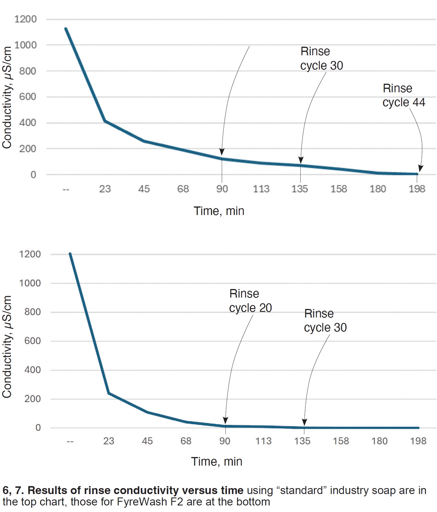
The product the plant had been using recovered 3.1 MW (corrected for ambient conditions) from the wash, conducted July 2023 using 32 gal of soap; 4.3 MW was recovered (corrected for ambient conditions) by washing with 36 gal of FyreWash F2 in April 2024. Number of rinses for the first test was 44, for the second, 30.
Project participant:
Glen Hicks, operations manager