Calls to the CCJ editorial office from Tucker York, SVI Bremco’s acoustical engineering guru, are always welcome. This outage season success story comes from a combined-cycle plant with chronic maintenance issues with the “egg-crate” turning vane weldment located in the HRSG transition duct immediately downstream of its 120-MW gas turbine. Over time, vane and support modifications intended to tame aerodynamic loading led to recurring weld failures and compromised flow conditioning into the first-stage, high-pressure (HP) tube module.
The plant contacted SVI for an engineering assessment of removing the vane set and substituting a simpler, more robust flow modifier in the aft half of the transition duct, such as a perforated distribution plate or a deflector (kick-plate). The objective was to preserve acceptable flow distribution and thermal performance while reducing structural risk and maintenance burden.
Why uniformity matters
HRSG performance and reliability depend on how evenly exhaust is presented to HP, IP, and LP bundles. Maldistribution drives localized hot spots, uneven heat transfer, elevated thermal gradients, and tube-to-tube temperature differentials. Consequences include fatigue cracking, accelerated oxide growth and spall, creep damage in hot zones, and elevated pressure drop where local velocities run high. For operators, the practical signals are familiar: rising ΔP, unstable attemperation, drifting stack temperature profiles, and repeated tube repairs.
Properly conditioned flow into the HP inlet face supports:
- Uniform heat pickup across the bundle face for steadier steam generation
- Reduced thermal fatigue by avoiding persistent high-velocity jets
- Controlled pressure drop that preserves combined-cycle back-pressure margins
- Longer component life by limiting erosion, vibration, and dynamic loading
Modeling approach, assumptions
Using CFD modeling to evaluate the exhaust path from the gas-turbine diffuser through the transition duct to the front of the HP bundle allowed testing “what-ifs” without welding anything: keep the vanes, remove them, or add simple flow modifiers. The tube bundles were represented as porous blocks (to reflect real pressure drop), and the inlet swirl that GTs typically deliver was included so results matched field behavior.
The main scorecard was how even the face velocity is at the HP inlet. Measuring the percentage of area within ±15% of the average velocity is a practical way to compare cases on the same footing. The OEM geometry served as the baseline for judging improvement.
Baseline vs removal: what changes
With the OEM egg-crate vanes in place, 33.5% of the HP face was within the target band. Pulling the vanes with no replacement dropped that to 18.0% and created bigger recirculation and high-shear zones. In other words, taking the vanes out may cure weld failures, but it invites hot streaks and localized high velocities—not a good trade for tube life.
Iterating toward simpler modifiers
SVI Bremco then evaluated the following options for deflectors and perforated plates, hardware easier to fabricate, install, and service than multi-piece vane weldments:
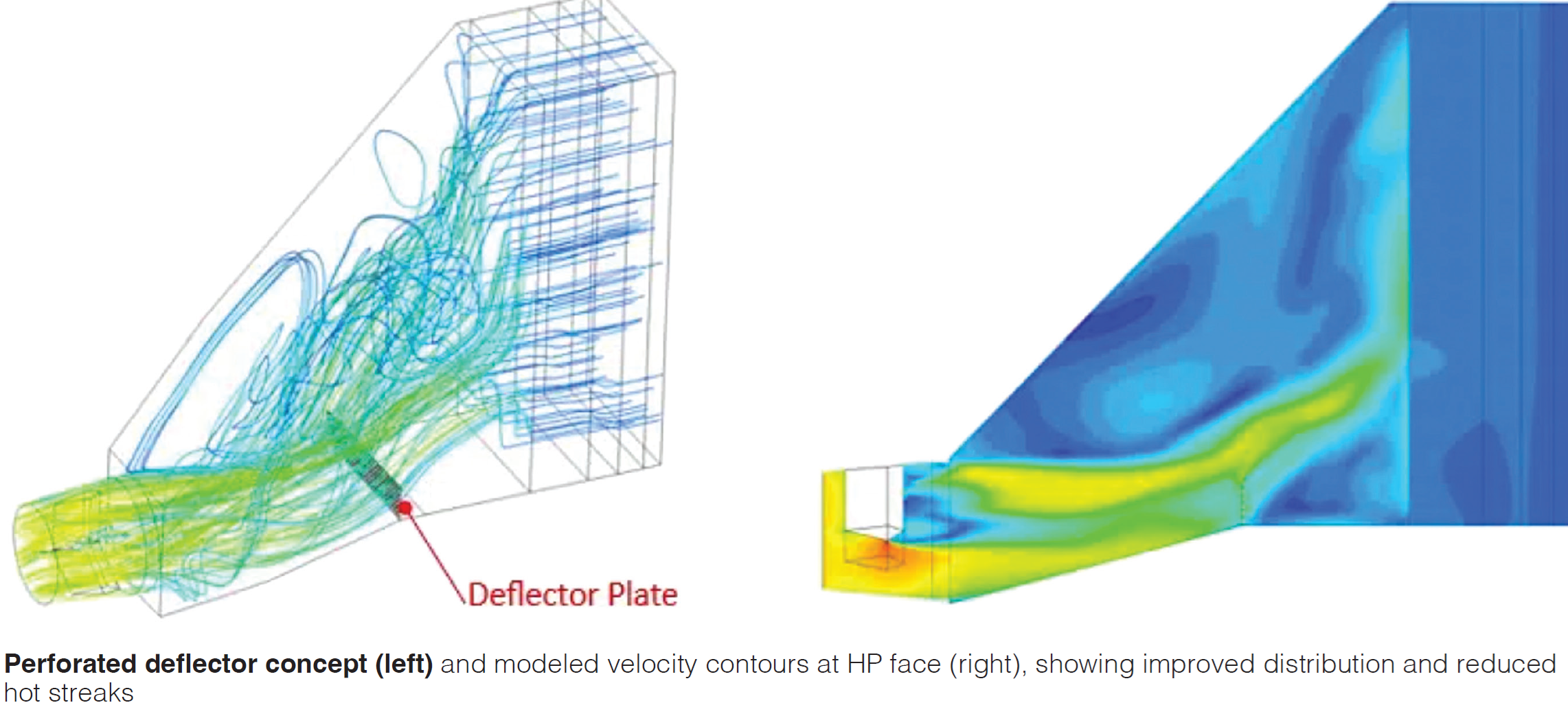
- A 36-in deflector with 4-in holes (~15.7% open area) and a serrated top edge improved uniformity to ~29.9%, though there was a predictable wake right behind the plate
- Increasing height to 48 in and open area to ~37% (larger perforations) lifted uniformity to ~30.8%. The serrations helped break up large flow structures, smoothing gradients
Bottom line: a perforated, serrated deflector reliably pushes flow toward under-served regions and tames extremes without the complexity of vanes.
Alternative concept: partial distribution grid
A tall, perforated grid (~114 in) performed best in modeling, ~45.7% in-band with acceptable modeled loss, but site realities dominated: higher loads, tougher installation, and maintenance safety concerns. The incremental uniformity did not outweigh those risks.
Recommended implementation and practical notes
The preferred solution is a 48-in-tall, perforated deflector (about 37% open area) with a serrated top edge. Depending on fabrication preferences, 4-6-in holes will typically hit the open-area target while keeping plate stiffness reasonable. This choice balances better distribution, simpler structure, easier access, and safer maintenance (Figure). While the uniformity does not reach textbook best-practice ranges, it replaces a failure-prone vane set with rugged, serviceable hardware and reduces thermal-mechanical risk at acceptable cost and complexity.
What operators should consider at their sites
- Establish a plant-specific distribution metric. Use a consistent in-band definition and pair it with stack temperature scans, bundle ΔP, and attemperation behavior to ground the model in operating data
- Include realistic swirl. Gas-turbine exhaust rarely enters the HRSG axially; small inlet angles can dominate downstream flow structure.
- Model porous bundles. Resolving every tube and fin is not practical; validated porous coefficients and duty sinks give useful answers with tractable meshes.
- Right-size the modifier. Taller or denser grids can raise uniformity, but loads, constructability, and confined-space safety may govern.
- Plan for inspection and repair. Simpler plates with serrations and controlled open area often provide the best life-cycle value where access is limited.
- Track results. After installation, trend ΔP, thermography, and tube repair patterns to validate benefits and refine future designs.
For HRSG transitions that have struggled with turning-vane durability, straightforward flow modifiers offer a credible path to maintain thermal efficiency without re-creating complex weldments. A modest, perforated deflector plate can reduce structural risk, simplify outages, and improve distribution enough to protect bundle life, provided that site loads, access, and safety are addressed early in the design. CCJ