The 7EA gas turbine’s many attributes—including generally high reliability and availability, and good efficiency in a wide range of applications on a variety of fuels—help make it the most popular mid-size (nominal 85 MW) industrial gas turbine. There are said to be about 1200 of these machines in service.
Annual meetings of the 7EA Users Group attract more than a hundred attendees, representing owner/operators from across the globe, to share experiences. Inspections and overhauls typically are a focal point of interactive discussions among users. Virtually everyone in the room wants to know what issues to be aware of, where they are likely to occur, what the indications look like, how frequently their engines should be inspected, etc.
The editors corralled Mike Hoogsteden, director of field services for Advanced Turbine Support LLC, which inspects scores of these machines annually, to learn how users can make their outages more productive and minimize the possibility of missing something that could contribute to a forced outage.
A good place to start, he said, is to review the OEM’s Technical Information Letters (TILs) pertaining to the 7EA, take notes, and bring your questions to the next user-group meeting. Your colleagues and participating suppliers are the best source of advice on what’s important and what’s not, Hoogsteden added. The knowledge gained will help you plan the optimal outage for your gas turbines.
Five TILs he suggested users become intimately familiar with are these:
-
-
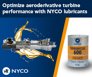
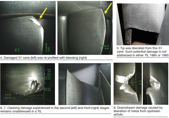
- 1884, “7EA R1/S1 Inspection Recommendations,” which addresses the need to inspect R1 and S1 airfoils for possible damage caused by clashing—the unwanted contact between S1 stator-vane tips and R1 rotor-blade roots during operation.
- 1980, “7EA S1 Suction Side Inspection Recommendations,” which advises users to inspect for crack indications on S1 vanes made of type-403 stainless-steel, regardless of whether clashing damage is in evidence on S1 and R1 airfoils.
- 1854, “Compressor Rotor Stages 2 and 3 Tip Loss,” which suggests blending and tipping to mitigate the impact on availability and reliability of R2 and/or R3 tip loss. This TIL supplements information provided by the OEM in the O&M manual provided with the engine.
- 1562-R1, “Heavy-Duty Gas Turbine Shim Migration and Loss,” which informs users on the need to monitor the condition of compressor shims and corrective actions available to mitigate the risks of migrating shims.
- 1744, “S17, EGV1, and EGV2 Stator-Ring Rail and CDC Hook Fit Wear Inspection,” provides guidance on the repair of dovetail wear and suggests hardware and software enhancements available to mitigate the potential risk caused by operating conditions that promote such wear.
-
There are many more TILs that demand your attention, to be sure. They include the following:
-
-
- 1090-2R1, “Compressor R17 Blade Movement.”
- 1067-R3, “Stage 2 Bucket Tip Shroud Deflection.”
- 1634, “Stages 2 and 3 Bucket Low-Speed Rub Prevention.”
- 1313, “Stage 3 Bucket Tip Shroud Overlap.”
-
TIL 1884
It took years for the OEM to address clashing in a TIL (Fig 1). Hoogsteden believes Advanced Turbine Support was the first company to alert the industry to this phenomenon—back in 2006. TIL 1884 was issued in spring 2013. During the intervening years, Advanced Turbine Support worked closely with the users to share inspection data important to problem definition and solution.
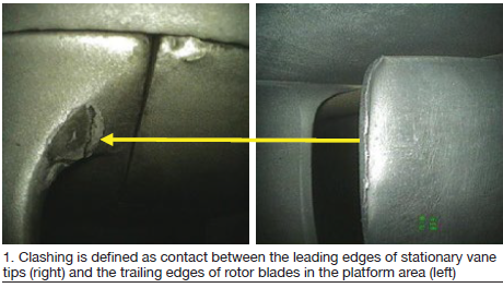
 Developments in inspection technology contributed to a better understanding of first-stage findings and provided information of greater value for the resolution of issues. Follow this timeline: 2008, implementation of visible dye inspections; 2009-2010, measurements added to documentation (Fig 2); 2011-2012, inspection documentation with trending data reveals an obvious increase in damage year over year. Plus, the implementation of eddy-current (EC) testing suggests an elevated level of risk to owner/operators.
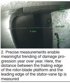
TIL 1884 went beyond clashing, recommending the checking of stator vanes for cracking in the co-called “area of interest” (Fig 3). Lock-up of vanes in carbon-steel ring segments can cause higher-than-normal operating stresses, which the OEM says “reach a maximum on the suction side of the vane near the mid-chord location.”
Cracking was first reported after TIL 1884 was published. In spring 2014, Advanced Turbine Support identified by way of dye penetrant two cracked S1 vanes in the same compressor. EC confirmed the findings. The company’s inspectors found cracks in more machines over the next several months. This experience revealed that some cracks can be too fine to bleed penetrant, as recommended by the OEM; however, EC was able to find them.
Hoogsteden’s suggestion to mitigate the possibility of serious damage from clashing and cracking is to perform an in-situ EC inspection to the trailing edges of all R1 rotor-blade platforms and the entire suction side of every S1 stator vane from platform to tip each peak-run season or every six months.
TIL 1980
TIL 1980, issued in January 2016, is viewed by the editors as an “addendum” to TIL 1884, addressing S1 vanes installed in legacy 7EAs (1996 and earlier) made of Type 403 stainless steel. This material is more susceptible to mid-chord cracking than the GTD™ 450 alloy used in the manufacture of vanes since 1997.
TIL1980 recommends inspection by visible means or by fluorescent dye to reveal suction-side cracks that might be present. Hoogsteden mentioned in his comments on TIL 1884 that these methods are inferior to EC for this purpose. He added that if the vanes are coated, visible or fluorescent dye penetrant inspections may not be dependable, nor have an acceptable probability of detection.
Regarding the effectiveness of ultrasonic (UT) inspection for this purpose, if coating degradation—such as disbanding—occurs, the value of UT could be compromised.
Advantages of EC Array include the following:
-
-
- It can detect crack initiation faster than UT.
- For coated vanes, the inspection equipment used by Advanced Turbine Support has the ability to maintain accuracy in flaw sizing (length and depth) for coating thicknesses of up to 0.125 in.
- Superior to in-situ liquid-penetrant inspection, which may miss small cracks.
- Two scans cover the entire suction face of a 7EA S1 vane.
-
Ultrasonic phased array can be used to supplement any suspect indications to confirm sizing of larger/deeper indications. But keep in mind that the UT probe does not cover the entire width of the stator vane—only about 0.75 in.
Hoogsteden went on to describe some of the damage found during its TIL 1884 and 1980 inspections, which go beyond what the OEM suggests. These are shown in Figs 4 through 8.
TIL 1854
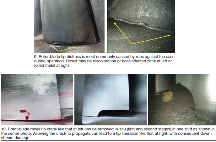
TIL 1854, released in August 2012, informs owner/operators of E-class compressors about the blending and tipping of second- and third-stage rotor blades it recommends to mitigate the negative impact on availability and reliability caused by tip loss from heavy rubs (Fig 9) and/or corrosion pitting.
The OEM says fleet experience and engineering analysis have concluded that compressor rubs can be caused by casing distortion that progresses over time, and by hot restarts initiated between one and eight hours after shutdown. The latter causes critical clearances to decrease. Corrosion pitting, by contrast, can create a local stress concentration that may result in tip loss via high-cycle fatigue.
Hoogsteden pointed out that although this advisory does not address first-stage rotor blades, they too can suffer tip loss and should be included in your inspection regimen. For R1 and R2 rotor blades showing signs of tip distress, Advanced Turbine Support recommends, at a minimum, a visible dye-penetrant inspection to determine if radial cracks have initiated (Fig 10). For R3 blades, the company recommends a minimum of a 360-deg roll with a close-up inspection of all blade tips at the same intervals.
The editors asked the field-service director why his company espouses such conservatism when the OEM doesn’t. He said their recommendations are based on more than 1000 in-situ visible dye-penetrant inspections which have identified at least 64 cracked rotor blades and about half as many tip liberations.
TIL 1562
TIL 1562, issued January 2007, is likely the most familiar of the advisories in this group of five because it is more than a decade old and shim liberation has been discussed frequently in user-group meetings and in CCJ. Fig 11 provides a quick review. The left-hand drawing is of a typical shim, center photo shows a shim protruding from the compressor, right-hand picture is of a shim blended flush to the case because it couldn’t be removed completely without difficulty.
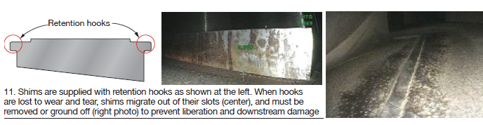
Hoogsteden recommends that users develop a shim map for their compressors to identify locations where shims might have been installed, then audit those locations for shims remaining. The map should be updated after every inspection. Shims protruding from the case by less than one-quarter of an inch should be monitored regularly. When the shim protrudes into the flow stream one-quarter of an inch or more it should be removed or ground off.
TIL 1744
TIL 1744, issued September 2010, said 7EAs operating at part load when ambient temperature is less than 40F are at risk for major damage caused by the lifting of 17th-stage vane segments. As the segments lift up they damage the hook fits and turn into the rotating blades.
A non-OEM repair procedure described at a user group meeting attended by the editors involved milling of the damaged slot to accommodate 18-in. inserts. They were installed in the upper and lower halves of the case to retain the new vane segments. The inserts are held in place with setscrews. The user describing the procedure cautioned against considering it a permanent fix because a root cause analysis had not been completed.