

By Jeff Porubcan, in conjunction with representatives from Mitsubishi Power, EPRI, and Georgia Power
Editor’s note: Hydrogen has moved past white-paper status and onto utility hardware. At Plant McDonough-Atkinson, Southern Company and its partners pushed a converted M501GAC gas turbine to hydrogen blend levels and flow rates that matter to combined-cycle operators, not just lab programs.
Why now? Because flexibility, emissions pressure, and renewables are forcing owners to look harder at fuels that can widen operating options without replacing the asset base.
The article that follows gets into the hard part: pressure control, code compliance, safety, combustor changes, and system integration. Those are the issues that will decide whether hydrogen co-firing becomes a talking point or a valuable plant tool.
Introduction
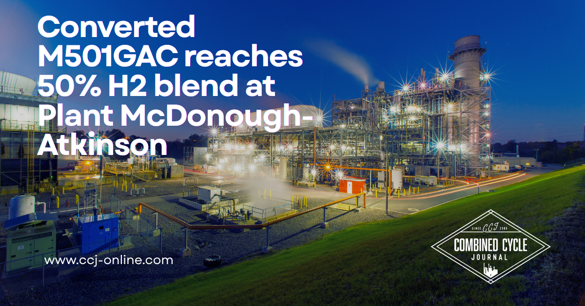
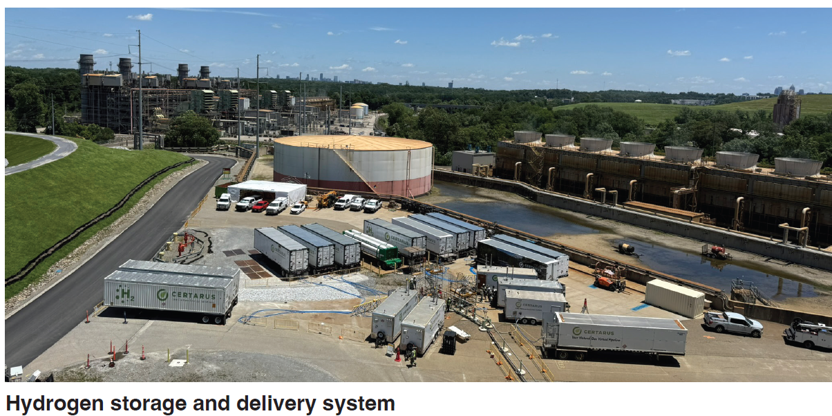
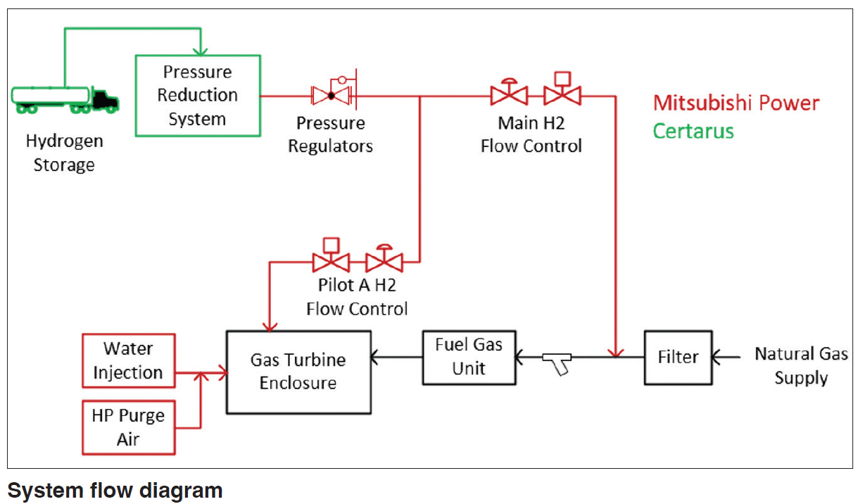
In 2025, Georgia Power (a subsidiary of Southern Company), Mitsubishi Power, Certarus, and EPRI conducted a large-scale hydrogen (H2) blending demonstration on a M501GAC advanced gas turbine in combined cycle configuration at the McDonough-Atkinson power plant in Smyrna, Georgia. The purpose was to showcase the fuel flexibility and co-firing capabilities of the M501GAC gas turbine [4]. The unit, originally a 501G, was retrofitted to support H2 blends up to 50% by volume across multiple fuel circuits within the Dry Low NOx (DLN) combustion system. The demonstration achieved the highest documented H2 flow rate in a utility-scale turbine to date—exceeding 10,000 lbs/hr—enabled by a complex infrastructure comprising 11 H2 mobile storage units, four pressure reduction. skids, and a custom-designed H2 flow and blending, fuel delivery, and control system.
Independent regulation of H2 blend ratios for multiple fuel circuits was accomplished using an advanced fuel gas blending system made up of flow meters, control valves, and pressure relief devices — all automatically controlled via custom-designed logic. The system design addressed key technical challenges including pressure management, equipment protection, and safety systems under high-flow conditions. Compliance with ASME, along with other piping, storage, and safety codes, required careful interpretation to ensure overpressure protection was met while maintaining operational flexibility.
This article presents the system architecture, design considerations, and operational results from the demonstration, offering insights into the practical integration of high-volume H2 with existing gas turbine infrastructure. The findings can inform future retrofits and H2 co-firing projects aimed at decarbonizing large-scale power generation.
Project background
Plant McDonough-Atkinson, which was commissioned in 1930 and serves the greater Atlanta, Georgia region, operates three 2 x 1 combined cycle power blocks, with a total generating capacity of more than 2,700 megawatts (MW). With Georgia experiencing extraordinary economic growth, operating flexibility of Plant McDonough-Atkinson has become increasingly important. Co-firing with H2 fuel has the potential to provide greater operational flexibility, as it increases gas turbine load turndown capability, potentially resulting in fewer shutdowns during times of low power demand and lower natural gas consumption.
Hydrogen is currently more expensive than natural gas, but during periods of low market demand, non-dispatchable power, which may otherwise be curtailed, can be used to produce and store H2 gas, thus making it more economical. H2 blending also offers environmental benefits, as its combustion does not result in carbon dioxide (CO2) emissions, as shown in the chemical reaction below:
[2𝐻2 + 𝑂2= 2𝐻2𝑂 + ℎ𝑒𝑎𝑡]
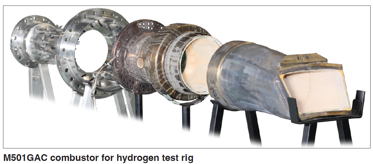
Southern Company has been at the forefront of large-scale H2 fueling applications, recognizing the impact H2 blending demonstrations can have on the industry as it moves to decarbonize. Building on a previous 20% H2 co-firing demonstration at Plant McDonough-Atkinson in 2023 [3], Southern Company had an ambitious goal to achieve 50% H2 co-firing (by volume) at the same location. Doing so required modifications to the gas turbine, primarily converting from a steam-cooled combustor to an air-cooled combustor. The conversion provides the added benefit of reducing the cold start-up time for the gas turbine (since steam warming periods are eliminated).
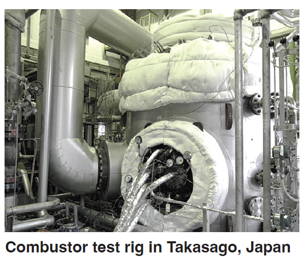
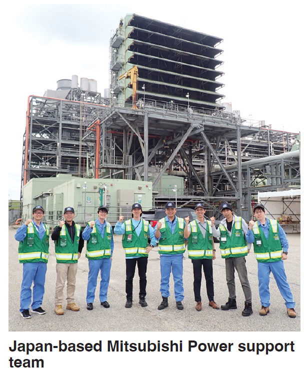
Increasing the pilot ratio and injecting water for NOx emissions control were the primary mechanisms for achieving 50% H2 co-firing. The success of the project was made possible by extensive combustor research and development and rig testing performed in Mitsubishi Power’s headquarters in Takasago, Japan.
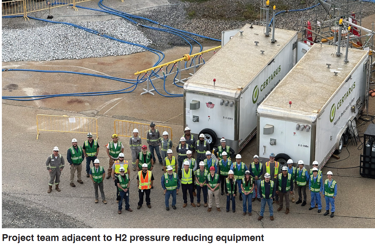
The project team included personnel from Georgia Power, Mitsubishi Power, and EPRI. Several specialized contractors, designers, and equipment vendors were also enlisted for support. The main goals of the demonstration were to:
- Achieve safe and reliable operation with H2 blending
- Demonstrate wet combustion at 50% H2 by volume
- Demonstrate dry combustion at 30% H2 by volume
- Determine the emissions and turndown effect from H2 introduction into the natural gas fuel stream
System design considerations
Along with gas turbine conversion, several new auxiliary systems were required for the project including (but not limited to) mobile H2 storage, H2 pressure reduction, H2 flow control stages, H2 blending, high-pressure purge air, water injection, nitrogen purge, control oil, trip oil, instrument air, etc.
The infrastructure additions for the 50% co-firing demonstration were more significant than the previous 20% co-firing project. This was driven by two main factors: 1) H2 injection into multiple fuel stages and 2) the requirement for NOx reduction system(s).
Hydrogen pressure control was challenging due to existing system constraints. A very narrow pressure window (~30 psi) exists between the required pressure for operation and the existing fuel gas piping system design pressure. While this was not an ideal operating scenario, it was manageable.
Overpressure protection is required by various codes (e.g., ASME B31.12 [7], B31.1 [6], API 521 [10], NFPA 2 [11]). It typically is accomplished using a full flow sized relief valve. However, a full flow relief valve was not desired for several reasons, including a very high-pressure safety valve (PSV) reaction force, large discharge piping size, risk of large H2 release (resulting in noise, possible deflagration, etc.), lack of redundancy, and the potential for a PSV release to trip the gas turbine.
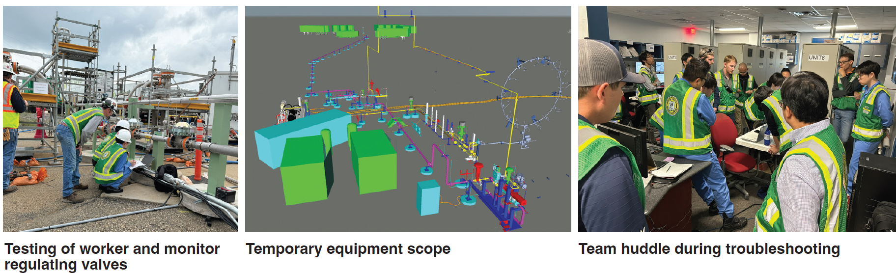
During the previous 20% demonstration, implementation of a full flow relief valve was complicated and arduous. To avoid this during the 50% demonstration, an alternative protection method was chosen which relied on three main components: 1) tandem gas regulators, 2) a trip stop valve, and 3) a small safety pressure relief valve (sized for leakage flow only).
Ultimately, this method was used with worker and wide-open monitor pressure-regulating valves, which allowed for failure of any single control device. The tandem pressure regulator configuration creates a controlled, layered safety strategy that meets ASME B31.12 requirements for H2 systems without requiring full-area venting.
In the arrangement, the primary worker valve fails open and the back-up monitor valve fails closed. During normal operation, the back-up monitor valve pressure is set slightly higher than the primary valve, forcing the monitor valve to fully open. If the worker valve fails, the spring forces it open. As the downstream pressure increases above its set pressure, the monitor valve takes over control. Primary regulator failure is detected via an increase in the downstream control pressure.
Trip stop valve(s) functionality was satisfied by adding a feature to the shutoff valve, which required a special style of solenoid valve with manual reset. Upon reaching the trip pressure, the solenoid valve, (hardwired from a pressure switch) de-energizes and locks out. The trip stop valve then slams shut and can only be opened after manually resetting the solenoid via a local reset button. This feature was intentional and required by code.
A PSV was also required to protect against leakage through the regulator valves. The leakage rating of the regulators (class II [8]) only required a small orifice, limiting the amount of H2 released. A direct-acting pressure relief valve was not feasible due to the poor seat tightness approaching the set pressure (leak-tight up to 90% of set pressure). To avoid constant leakage to atmosphere, a pilot-operated relief valve was used instead (leak-tight up to 98% of set pressure). Both types are allowed under ASME BPCV Section XIII [5].
All new H2 piping was designed and manufactured in accordance with ASME B31.12 and B31.1 codes. However, H2 gas was also introduced into many existing piping branches, which were originally intended for natural gas, and thus manufactured in accordance with ASME B31.1 code only. The existing piping was evaluated for conformance to the B31.12 H2 code using a gap analysis. Hydrogen embrittlement and stress corrosion cracking are known problems with H2 pipelines. Mitigating these risks required evaluation of existing piping hardness values, especially at weld joints and cold bends.
Auto-ignition (due to the high temperature) was another important risk factor that was considered in the design process. Some gas turbine fuel supply lines have transient conditions where fuel is displaced with hot combustion air. For the demonstration at Plant McDonough-Atkinson, these conditions were intentionally avoided by sequence of operations. Nonetheless, a detailed auto-ignition study was conducted in conjunction with the University of Central Florida (UCF) to evaluate the impact of fuel blend ratio, pressure, and temperature [1,2]. The results were used to determine the logic control setting values to trip the gas turbine.
Creating the new H2 system(s) presented challenges, especially considering the temporary nature of the project. Atypical system requirements included execution duration (installation and removal), lead time, space restrictions, power supply, control system compatibility, etc. These requirements were considered early in the design phase, which facilitated smooth execution.
Numerous factors were considered when designing the layout of the new temporary systems, including emergency egress, new hazardous areas, NFPA 2 equipment setback distances, access for normal plant operation, and all normal service-related equipment and tooling (e.g., cranes, laydown space, etc.)
With the addition of H2 into the existing fuel gas piping, established hazardous area release points (Class I Div 2 Group D) had to be reclassified for H2 gas release (Class I Div 2 Group B). Therefore, all electrical (and mechanical) equipment and installation within the hazardous areas was studied in detail. Several electrical devices were not compatible with H2 and were replaced with suitable equivalents.
Hazardous areas onsite were originally determined using API 500 [9], which carries different definitions than NFPA 70 [12]. Two key differences worth noting are the discharge point plume radius and flange connections (API 500 does not consider flanges a leak point). Nonetheless, all flanged connections were examined as potential leakage points, and all equipment within the larger NFPA 70 radii was evaluated. This led to some additional modifications.
Plant safety
Safety was a top priority for the demonstration project. Thus, the properties of H2 gas which present additional risks relative to natural gas (e.g., low ignition energy, wide flammability range, small molecular size, invisible flame, non-odorous, buoyancy, etc.) were considered and mitigated. Hydrogen has been used for decades in plants with H2-cooled generators. The industry is familiar with designing and operating systems to support these applications. However, for the new H2 supply system at Plant McDonough-Atkinson, hazardous operations reviews were conducted, which yielded several additional safety precautions, including:
- Equipotential bonding. All flange joints were equipped with a metallic bonding connector from one flange to the other, including any items between the flanges. Resistance was measured and verified to be below allowable limits for all flange joints.
- Leakage simulation. A Computational Fluid Dynamic (CFD) model was created to evaluate H2 leaks at all flanged connections inside of the gas turbine enclosure. The result was used to improve air circulation.
- Gas detection. Natural gas detectors monitor the ambient air inside all enclosures that contain natural gas. These devices remained active, with an additional set of gas detectors installed to detect H2 leakage. The selected H2 gas detectors were significantly more sensitive than natural gas detectors and could detect lower explosive limit (LEL) levels. All detectors were calibrated before use with laboratory grade test gas.
- Cleaning. Due to the insulating and low ignition energy properties of H2 gas, any debris in the pipeline could accumulate static charge and potentially cause unintended ignition. Therefore, extensive cleaning measures were taken after fabrication, including solution passivation, manual cleaning, and air blows [13].
- Leak testing. After assembly, the entire H2 pipeline was leak tested at design pressure using a uniform blend of helium and nitrogen gas. Helium gas (the next smallest molecule) is an inert gas and was used for leak detection employing the soap bubble technique, along with a very sensitive helium gas sniffer device. This, combined with a robust flange torquing procedure, ensured that all connections were leak-tight prior to introducing H2. Furthermore, after H2 was introduced, the entire system was routinely inspected for leaks using sniffer probes.
- Hydrogen sensitive tape. All flanged joint cavities were sealed with nuclear-grade duct tape. A pin hole was placed in the tape and then covered with H2 leak detection tape. The tape allowed for visible indication of any H2 leak. No leaks were detected throughout the demonstration.
- Purging and inerting. A detailed process for filling the H2 piping was established and followed. Before any H2 was introduced, the piping was purged and vented with an inert gas (nitrogen) repeatedly until the oxygen content in the pipe was below the fuel/air mixture flammability level (2.76% O2). This was verified using a specialized gas sampling instrument and measuring the oxygen content in several different piping locations. Similarly, after H2 was introduced, the inert gas was displaced until pure H2 concentration was achieved. At no point was pressure allowed to drop below 5 psig, thereby preventing air from entering the pipeline.
- Restricted access and signage. When the system was charged with H2 gas, personnel access was restricted into the power block. Road barricades and warning signs with contact information were posted at all access points.
- Specialized tools. Any work that was to be performed with the H2 system online required the use of specialized “spark-free” hand tools.
- Communication. Clear communication was essential to successful execution. Special radios were procured for use in hazardous environments. During the first communication checks, it was found that radios could not transmit consistently between the test area and control room. Testing was halted until the issue was resolved by adding a digital signal repeater.
A specific radio communication protocol was also established: messages were delivered and repeated, and recipients were required to provide verbal confirmation to ensure accuracy. In addition, AlertMedia was utilized to notify site personnel when testing was in progress, ensuring broad awareness and timely updates across the facility.
Test execution and lessons learned
Execution of the 50% H2 co-firing demonstration did present unique challenges. Preparation for each test was careful and precise. A written procedure identifying all sequential steps and hold points was reviewed and agreed to by all parties. The procedure identified clear roles, responsibilities, and hold points for each step in the procedure. Before and after each test, the team performed a pre-brief and de-brief, where the day’s events were discussed. Emergency action plans and lessons learned were also covered, while still fresh in memory.
Several unplanned events occurred during the test period which caused delays. Some of these were external and could not be controlled, including inclement weather, lightning strike damaging controls equipment, grid demand (dispatch), and unplanned balance of plant (BOP) maintenance.
During testing, it was learned that self-contained pressure regulators should have a local vent line and a small throttle valve to bypass the main supply isolation valve. As the H2 piping pressure was increased to the set pressure, the (fail open) worker valve began to close, but slower than anticipated. During initial testing using nitrogen and CNG, the worker and monitor regulators did not respond fast enough and caused the downstream pressure to spike past the setting, opening the PSV. Consequently, the test procedure was modified for a very slow fill rate.
In addition, the narrow operating pressure window was exacerbated by the weather. When the H2 pipeline was on standby (i.e., pressurized, no flow), solar load on the piping caused the gas to expand and pressure to rise. Even with the worker and monitor regulator valves closed, the combination of leakage flow and solar loading caused the downstream pressure to slowly creep towards the trip pressure setting. While the trip stop valve and PSV were in place to protect the system from overpressure, it was preferred to keep the system active by manually venting the gas. Piping insulation may have prevented this but was not considered due to other factors.
For simplicity, multi-variable flow transmitters were used to send pressure, temperature, and flow signals to the control system. In these devices, primary signals are analog (4-20mA), and secondary, tertiary, and quaternary signals are HART burst data. Unfortunately, erratic discontinuity of HART burst messaging signals was observed. As this issue was difficult to troubleshoot and led to lost time, burst messaging in a control circuit is not recommended for future projects.
Refueling the 11 H2 mobile storage units was a challenge as well. Refueling of the tractor trailers occurred four times, each requiring four days of logistics. Between tests, the gas turbine operated in normal dispatch. For additional safety, the H2 system was completely vented and purged with inert gas after each test. The time between tests was used to carefully evaluate the previous test data and make any adjustments to control parameters.
Despite these obstacles, all primary goals of the demonstration project were achieved, and the benefits of H2 co-firing exceeded expectations. Wet co-firing at 50.2% H2 by volume was successfully completed at base and partial loading conditions, as was dry co-firing at 30% H2 by volume. Gas turbine minimum compliance load was successfully reduced to 35% with the assistance of H2 co-firing, enhancing operational flexibility. Over 25,000 lbs of H2 was consumed and over 170,000 lbs of CO2 emissions was avoided throughout the duration of the test.
Advancing H2 GT applications
The demonstration at Plant McDonough-Atkinson represents a significant milestone in the progressive development of H2 operation within utility-scale, natural gas-fired power plants. Building on the previous 20% H2 co-firing demonstration in 2022 and other industry trials, the 50% H2 demonstration further extended the operational envelope of the gas turbine and validated advanced combustor designs, fuel blending systems, and safety strategies under real-world conditions. EPRI has been involved in numerous H2 demonstrations. The primary goal of these collective efforts has been to advance the industry forward and document lessons learned so that new knowledge can be applied on future projects.
In summary, by successfully demonstrating high mass flows and H2 blending percentage integration at scale, the co-firing demonstration at Plant McDonough-Atkinson provided critical data and operational experience that will inform future retrofits, guide combustor development, and accelerate the decarbonization of gas-fired power plants.
References:
- Loving, C., Mastantuono, G., Terracciano, A. C., Rahman, R. K., Kim, G. Vasu, S. S., Pigon, T., Hernandez, A., and Cloyd, S., 2025, “Extended Testing of the Auto-Ignition Characteristics of Hydrogen–Natural Gas Mixtures for the Safety of Power Plants”, ASME Paper No. GTP-24-1388
- Loving, C., Mastantuono, G., Terracciano, A. C., Vasu, S. S., Pigon, T., Hernandez, A., and Cloyd, S., 2023, “Auto-Ignition Test Results of Hydrogen and Natural Gas Fuels at Atmospheric and Elevated Pressures for Gas Turbine Safety,” ASME Paper No. GT2023-102674
- Georgia Power, 2022, “Georgia Power, Mitsubishi Power, EPRI Complete World’s Largest Hydrogen Fuel Blending at Plant McDonough-Atkinson,” Georgia Power, Atlanta, GA, accessed June 10, 2022
- Georgia Power, 2025, “50% hydrogen blend testing successfully completed at Georgia Power’s Plant McDonough-Atkinson,” Georgia Power, Atlanta, GA, accessed June 16, 2025
- ASME Boiler & Pressure Vessel Code (BPVC) Section XIII: Rules for Overpressure Protection
- ASME B31.1: Power Piping
- ASME B31.12: Hydrogen Piping and Pipelines
- ANSI/FCI 70-2 & IEC 60534-4: Control Valve Leakage Classes
- API 500: Sizing, Selection, and Installation of Pressure-Relieving Devices in Refineries
- API 521 part I: Guide for Pressure-Relieving and Depressurizing System
- NFPA 2: Hydrogen Technologies Code
- NFPA 70: National Electrical Code
- EPRI 1023628: Guidelines for Fuel Gas Line Cleaning Using Compressed Air or Nitrogen

