Among the portfolio of conferences under the umbrella of Power Users, the 2025 7F Users Conference certainly vies for the one with the most content shared directly from owner/operator (O/O) organization representatives. Which makes it especially valuable for the ~50% of attendees who were first timers. One key take-home tidbit: Most, if not all, of the following presentations are available to end users registered at www.powerusers.org.
Perhaps the most intriguing undercurrent to the content was the continued urging for more collaboration by O/Os to solve supply and delivery problems which, according to presenters, aren’t being addressed quickly enough by industry suppliers. Backing this up was an audience survey which revealed that aging assets and current supply and demand were far and away the top issues they are facing.
While two data points can make a line on a graph, they don’t necessarily support a trend but may be worth noting anyway. At least two of the largest 7F-based plant O/Os in the US have recently hired seasoned rotor experts away from the OEM, presumably to guide them through the thicket of rotor life evaluation (RLE), repair, and continued operation. One was a technical lead at the OEM, the other from the product and service team who was described as “having written most of the technical information letters (TILs) for 7F rotors.
As one of these experts noted in a panel discussion, “rotors don’t offer precursors before they do bad things.” Vibration analysis goes only so far.
O&M risks are not arising strictly from the major components either. One user lamented that delivery schedule to replace turbine wheel no. 1 tiebolt nuts was 57 weeks! That is, until the OEM came back with a field repair.
Another signpost of the times was a presentation on best practices for handling evidence that may support a root cause analysis (RCA) should the attendant failure lead to a legal dispute. The presentation was scheduled on the first morning of the first day.
Like CCJ’s report last year, this one begins with near-verbatim comments by the presenters to give the reader a sense of collective sentiment about their machines:
- TILs for the 7F.05 are coming fast and furious (and are originating from the OEM responding to issues with the HA machines)
- It’s a sellers’ market; the OEM wants to sell HAs rather than repair 7Fs
- How do we make a boneyard (a warehouse of usable components) available to users?
- Industry collaboration is needed to push past the 144,000 hrs/5000 starts limit set by the OEM for rotor life
- The OEM does not want to make compressor discharge casings
- All LTE refurbished rotors will come from overseas factories, adding months to the delivery schedule. An HA “slot” in the OEM’s US factory takes up 2FA slots.
- The OEM can do 13-15 rotors a year in its primary US facility, but these will be new units. It can do 50-60 worldwide, but that figure used to be 100+.
- Parts availability keeps us up at night
- Every part delivery is delayed, taking from 6-18 months.
- We’ve had ten non-conformance reports (NCRs) issued to the OEM in the last three months alone. Sometimes there are so many issues, we don’t even send in the NCRs.
- The OEM doesn’t want to order new parts (in this case coated segments of stator vanes) because it doesn’t have them
- The OEM has not “made schedule” on any rotor sent to its primary US manufacturing and repair facility
- Technical advisors for the BN3500 vibration monitoring rack have varied familiarity with the system. The system is getting obsoleted.
- Eight to ten users noted in a show of hands that they experience elevated temperatures in tilted pad generator bearings, a problem “we’ve been talking about for years.”
- Non-OEM suppliers are starting to have similar problems meeting parts demand and delivery schedules.
- Axial fuel staging (AFS) upgrade hardware adds seven days for tuning compared to the DLN 2.6.
Here’s a word of warning from an O/O rep presenting on a candidate for “catch of the year”: If you don’t have the enhanced compressor components (all 7Fs with an 18-stage axial unit), do the inspections recommended in TIL1509. Staff at this site found cracks in compressor blades which could soon have led to a catastrophic event.
The mood wasn’t all gloom and doom, however. One user, facing a recovery from a nasty forced outage in the end-of-year holiday period, reported excellent experience working with the OEM to get the unit back on-line quickly. Another reported that the OEM may be able to open up space for rotors at a different US factory location.
Other non-OEM suppliers are stepping up, too. PSM, now Hanwha Power, reported that it can now “get around” the OEM lockdown on model-based controls (MBC) with Autotune and FlexSuite control products. Doosan reported that it can refurbish 7F rotors for ten or more years of service and can “LTE overhaul a rotor in three to four weeks.” Doosan and PSM are cooperating to meet the industry’s need for replacement and refurbished rotors. And one user reported that field repairable compressor stage blading is now available.
Finally, at a time when even your dumbest cousin is mouthing off about how AI is going to rock our world, some words of wisdom from a veteran presenting a primer on combustion tuning: When you use remote tuning, you don’t feel and see what is happening with your machine. Translation: Automation and remote specialists are no substitute for the hands-on knowledge acquired by a plant operator becoming intimate with the machine. Every 7F may be the result of a “standardized” design and manufacturing process, but once it enters service, it becomes unique and responds differently.
Most user presentations, summarized here, are available to members at www.powerusers.org, and share invaluable best practices, lessons learned, experiences, updates on recurring issues, new issues to monitor, and post-mortem safety events which enrich the entire community.
Read the tea leaves. Kicking off the conference with an in-depth primer on the DLN 2.6 combustor hardware, flow diagrams, and tuning, the presenter urged his audience to “learn to read the tea leaves” of your components. For example, dark areas on combustion liners indicate poor air distribution and/or too much air leakage. Leaking air is often the root cause of NOx issues.
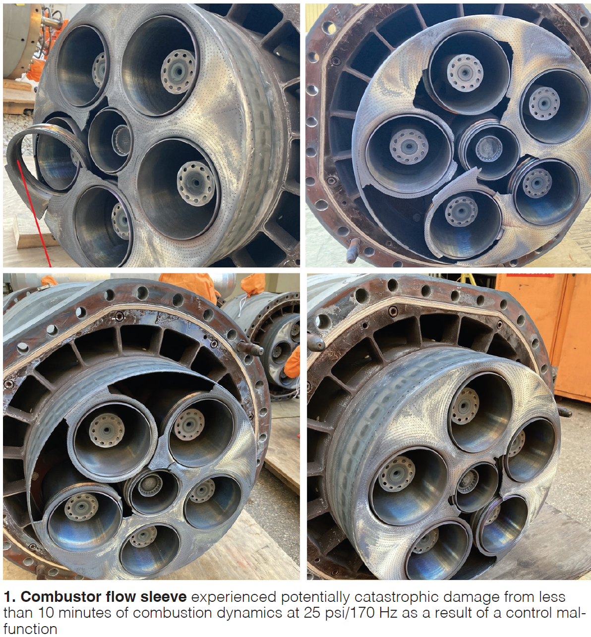
Discussion focused on essential terminology and potential issues with fuel/air ratios, tuning constants, combustion dynamics (Fig 1), leakage in compressor bleed (CBV) and inlet bleed heat (IBH) valves, part load operation, emissions, and axial fuel staging. Combustors are not as predictable as a gearbox, says the presenter; fire still has a “dimension of mystery.”
Don’t tamper with evidence. If a failure leads to a contractual dispute, all evidence must be properly preserved. The subsequent RCA will follow some version of the scientific method which includes data and evidence collection (all information related to the event and conditions), preservation and storage; proposed hypotheses which must be disproved and discarded; fault trees; and communication among the parties involved. Slides are chock full of best practices and practical recommendations, such as training in photography to best serve the RCA. Use of third parties can often limit the inherent biases of parties to the dispute. Slides include several excellent examples of failures and RCA.
Save of the year candidates
A hallmark of user conferences is the willingness of participants to share experiences involving injury or death to a worker, catastrophic or significant failures, and near misses. In the last category were two “save of the year” candidates.
On the fifth day before Xmas in 2024, operators noticed a step change in vibration from 0.07 in/sec to 0.36 in/sec on the 7FH2 generator T4 bearing (BB7 and BB8), not high enough to trigger an alarm, and coinciding with a step change in generator fan blade differential pressure (DP). Personnel hypothesized that the cause was a liberated fan blade.
Sure enough, there were no findings from a borescope inspection (BI) on the turbine end, but inspection of the collector end (T4) revealed a liberated cooling fan blade, and damage to the gas shield (fiberglass exterior with a balsa wood core) and stator end windings. What a time for a forced outage!
Nevertheless, the plant was back on-line by January 7, thanks to a coordinated effort between the O/O and the OEM, which was able to provide all the parts except the gas shield. Securing the gas shield, a challenging aspect of the recovery, was accomplished by having it repaired by a non-OEM firm and using ancillary parts from the OEM. The plant was lucky that the stator end cap could be repaired in situ.
Blade liberation was likely caused when the No. 1 bolt of cooling fan blade No. 5 broke because it was overloaded due to overtorqueing at install. The remaining No. 2 bolt could not hold the blade in place under cyclic stress forces and likely failed from fatigue (Fig 2).
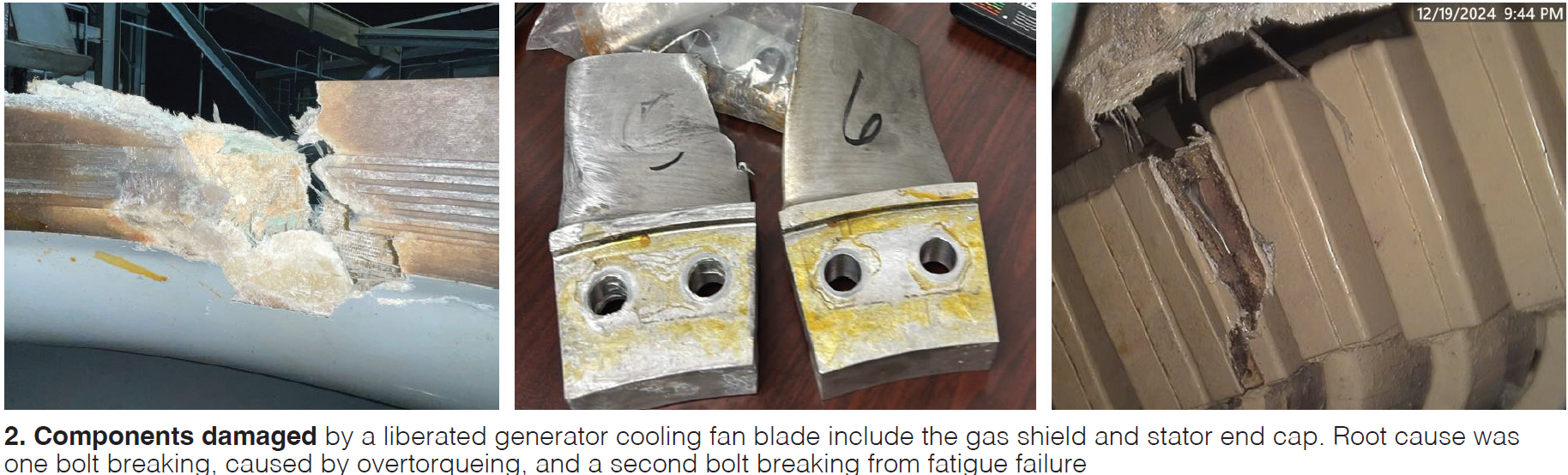
In response to audience Q&A, the presented noted that the last time these parts were “looked at” was in 2017, three years after the fan blades were installed and that they believe the unit had undergone a number of starts and hours “typical” of a ten-year period.
Words of wisdom from the presenter: Do not ignore the M&D alerts!
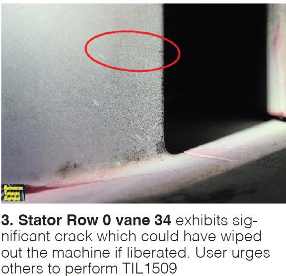
Avoiding a compressor wipeout. If your machine has non-enhanced compressor components, do the annual inspections recommended in TIL1509 R4, urges the presenter. Indications were found in one unit at his plant, with two 7F.03A peaking units, which could have resulted in a liberated S0 row vane and a machine wipeout. Those indications were not present a year ago and fifty starts earlier. Units have undergone relatively low starts and hours.
TIL1509 recommends the inspection because vanes can lock up and reduce damping, causing trailing edge distress. Locations vary between the root and halfway up the vane. Multiple cracks may be observed and several vanes may exhibit them. Vanes at bottom dead center are most susceptible. At this plant, vane 34 exhibited a significant crack (Fig 3). The plant underwent a forced outage and replaced S0 vanes and other stator rows, which had been in service for 15 years (and were “rusting”) with “enhanced” compressor components.
Presenter noted that insurance company was “very interested” in seeing this upgrade occur and that other users have been “encouraged” by their insuruers to replace original vanes with enhanced ones available from the OEM and one non-OEM supplier. During the Q&A, one seasoned veteran noted that these issues apply to both the flared and unflared compressors, and that one site did not replace the S3 row when they upgraded and it ended up failing. So, change out all stages when you upgrade.
Loss of lube oil event. In the category of significant loss, O/O rep from a site with four 7FA 1×1 CC units reported on a loss of lube oil event, while all four units were in startup, which led to a two-month outage for the affected machine. Subsequent inspections revealed damage of compressor tip curls, T1 and T2 bearings (babbitt melted down, journals wiped), and generator fan blades, bearings, and H2 seals.
Unit was at full speed no load (FSNL) when the lube oil pump (LOP) tripped on loss of pressure. The DC pump started but engaged too late. Low H2 pressure led to emergency purge. DC pump was manually shut down. The lead AC pump had previously failed and the standby pump failed during shutdown. During startup, the breaker would not close while the AC pump was running. Normal rolldown to turning gear takes 30 minutes; this one took 5 min.
The AC LOP 1 motor had failed three months prior and the LOP2 motor failed days before the event. During the startup sequence, the AC LOP operation was not physically verified. Opening a breaker on operating equipment under load is not normal procedure and contrary to arc flash avoidance, but the operator “was conditioned” to act as needed to get units on-line to meet dispatch.
Slides include a list of root causes to contributing factors and corrective actions. Audience Q&A focused on frequency of swapping out spared components (weekly, monthly) and component checks. One audience member noted they do DC oil checks quarterly. Presenter suggested that his site will now swap out spares on each start.
IGV hydraulic blowout. Workers at a baseload 2×1 CC site with 7FA.03 units (2002 vintage, but initial operation 2011) noticed an oil leak in the turbine compartment during a planned shutdown. Fortunately, the compartment was cool enough that no fire occurred. Initial investigation revealed that the servo valve detached from the IGV actuator via stripping of smaller bolts holding the device together (Fig 4). Around a 1000 gal of turbine lube oil was released, with minor escape through small cracks between floor and walls (though not reaching drains or ground).
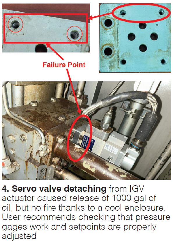 At conference time, the incident was being more thoroughly investigated, but the presenter offered a few theories, and as importantly, these suggestions:
- Make sure pressure gages on the low and high sides of the pumps are working and consider adding transmitters and trending them in the control room. At time of incident, local gages had topped out, and no trending is done, but it is believed that pressure surpassed 4000 psig.
- Ensure hydraulic PMs are conducted and confirm pressure setpoints. Periodically confirm relief valve operation.
This site replaces valves on a five-year cycle but this PM may change pending results from the investigation.
TURBINES
Imagine having CC units which now have to turn down to 22% (while still meeting 9 ppm NOx), from 58% two years ago! That’s what one O/O in a fast-growing region of the country faced when it underwent a 7FA fleet advanced gas path (AGP) upgrade and conversion to DLN 2.6 + axial fuel staging (AFS) + overboard bleed (OBB)in several units.
At one site, work was performed over a ten-year period. For the most recent AGP piece conducted in 2024 and 2025, 360 contractors and nine cranes were on site during a three-week outage. Slides provide key information on upgrade scopes and pre- and post-performance gains for two separate facilities.
Important O&M detail: After 4.5 years of operation, some DLN 2.6 hardware at one site exhibited small cracks (Fig 5) and had to be recoated, but the fourteen combustions liners and transition pieces “looked good.” One lesson learned is to anticipate unforeseen work, in this case exhaust frame leak repair and exhaust flex seal replacement.

At the other site (acquired in 2021), AGP, AFS, DLN 2.6, and OBB were undertaken during a massive three-month planned outage in 2024, which had to be extended by five months during the critical summer peak season. DLN tuning took 11 days, with the AFS adding seven days. Worth your time is the slide showing the additional outage scope and issues which prolonged the schedule.
7FA.04-200 upgrade pros, cons
“What the heck is a 7FA.04-200?,” this presenter asked rhetorically. He knows better than most since his O/O now has 30 of them, all converted/upgraded between 2015-2017. Features include a 14-stage compressor, a DLN 2.6, AGP Tech package, three stages of variable stator vanes, increase to 32K hours/1250 starts HGP interval (from 24K/900), and field replaceable compressor stage blading.
The benefits are considerable. Total power output per unit now surpasses (without power augmentation) 200 MW with a 3% heat rate improvement and improved startup and part-load efficiency. Value of replacing compressor airfoils in-situ was demonstrated when 54 blades were damaged. After effectively reaching the 1st HGP interval, only the liner caps (uncoated) needed replacement.
Listed as cons were the 45–60-day outage period needed for the mods, potential restrictions on generator and BOP, GT auxiliaries and BOP upgrades, and cost. Also, a fourth level had to be added to the inlet air housing. A maintenance note: HRSGs need to be cleaned more often because of the higher air flow through the unit.
Slides provide much more detail in photos, diagrams, and operational data.
R4P bucket upgrade
Updating a 2024 7F Users Conference presenter, this O/O rep, referencing two peaking facilities with modified 7FA.03s (AGP Tech), described a persisent issue since 2018: premature burnup of the first-stage blade leading edges on several units after less than 500 FFS and 1-4 years operation. Cause was diagnosed as loss of tip caps. The OEM’s two solutions – repair with the original tip caps, and repair with replaced caps – “appear to be effective” based on x-ray inspections.
The 2024 preso also noted another issue, platform cracks in 12 1st stage blades after 480 FFS and 5100 FFH. Since then, two additional units have undergone full S1B replacements because of this issue, one after 750 FFS/7800 FFH (installed fall 2018), the other after 420 FFS/3800 FFH (installed spring 2022). One other unit is forming platform cracks as well. The investigation process was in the RCA phase at conference time.
A third discovery was thermal barrier coating (TBC) spallation on the pressure side of the transition radius from platform to air foil. OEM attributed this to a coating process change that has since been corrected. Five sets of SB1s at the two facilities are affected. The O/O is keeping two sets in inventory in a warehouse should failures occur.
ROTORS
OEM veterans turned O/O specialists
Sports fans can recall what they feel when a favorite star player is traded to a rival team. That must have been what some in the audience were feeling when two OEM rotor design and manufacturing experts led a panel discussion as newly hired specialists for two O/O organizations each with dozens of 7Fs. This is when your attendance at user conferences becomes invaluable because generally there are no slide decks submitted for panels.
A few of the more salient points (not mentioned earlier) include:
- Casing alignment issues with older units are going to “bite and bite hard” when considering whether to push units to a 4th or 5th major refurbishment outage (144,000 hrs typically represents the 3rd major).
- Stator vanes are “always an inspection component.” If they aren’t locked up and don’t exhibit pitting, they can go on forever.
- The disassembly process itself can be damaging and impact life evaluation so ask yourself how often do you want to take the rotor apart.
- Expect more leaks in cooling air piping – pipe connections and manifolds are not making it to fifteen years life.
- What drives rotor life is what you can’t see inside.
- Don’t expect non-destructive examination (NDE) technology to improve fast enough to provide more assistance in rotor life evaluation, i.e., you can’t find 5 mil cracks with fluorescent penetrant (DP) or otherwise.
- 144,000 hrs (or 5000 starts) is the OEM defining a generic risk paradigm for you; you can define your own. Where you run and how you run matter greatly, and how often you subsequently take planned inspection outages (such as 24K vs 32K hours).
- BI inspections are not consistent across the fleet; some BIs are taking 2-3 days (although some parties can do a rotor BI in a day), and at least one user is doing BIs every six months.
- Blading on F.01 and F.02s are especially prone to galling and corrosion which must be addressed.
- Failure to start exacts a price in rotor life; if you don’t full start and properly shutdown and cooldown, you will regret it.
Rotor RLE findings. Major 7FA O/O rep reviewed experience and findings from RLE investigations for two rotors at the OEM’s Singapore facility, one with 134,000+ hours and 1680 starts, the other with 133,000+ hours and 1738 starts. Both have been extended to 240,000 hours and 5000 starts.
For both units, compressor aft shafts had to be scrapped and replaced (forward bolt face edge cracks), turbine wheel No. 1 (TW1) was replaced, turbine wheel No. 2 had new lockwire tab pinholes drilled, and the rabbit fits were given high velocity oxygen fuel (HVOF- a form of thermal spray) coatings. See slides for other findings and repairs.
An audience member (O/O rep) had just completed five rotor replacements, hoping to get twenty-five years of life out of them. He said that they start planning rotor replacements around the 100,000 hrs mark.
This user noted that one exhibited cracks on the aft side of the TW1 tiebolt nut and three units exhibited cracks on the forward side of the 12-point nut. He cautioned that they expect to find similar cracks in units at other sites. Another user suggested that the O/O have the OEM return the nut cut up for analysis.
Yet another audience member said during the Q&A that after initially stating that replacement nuts would take over a year when they faced this issue, the OEM came up with a new type of replacement. Refer to TILs 1937 and 1945.
7FA.05 Lightning round
Discussion moved from topic to topic, and TIL to TIL, so swiftly in the 7F.05 Breakout Session, it was hard to keep up. The root of the audience’s angst appeared to be the sheer number of TILs issued by the OEM, many based on adverse experiences with the HA units.
The list of TILs referenced include the newest (at the time) 2511 (compressor stator retention key), 2467 (Compressor blade circumferential gaps and locking), 2212 (spring loaded T fairings and low speed turning gear), 2133 (stator key deformation and ring segment migration), 2476 (stator 14 inspection, ID shroud, and brush seal), 2558 (stage 1 wheel), 1937, and 2019.
Some audience comments worth pondering:
- HA crews always bring new keys (TIL2511) because they expect the existing ones to need replacing.
- OEM is focused on stage 14 (TIL2476) but should be worried about others as well.
- Will the gap growth remain linear or begin to go exponentially (TIL2467)? It “gets scary” over 1.5 in.
- You’re going to find cracks – it will “light up like a christmas tree” under fluorescent penetrant inspection (TIL2476)
- How do you view the safety risk by implementing the TIL (2511)? You don’t get a choice, it’s a safety issue, and can add two days to the outage.
- The jury is still out on stator vane coated segments, and you can expect to need new coated segments every major.
- We are considering hook fit repairs at every HGP outage.
Regarding 7F.05 combustors, “the 3-D printed, phase 2 fuel nozzles are failing, and are not repairable (cast nozzles are repairable), “we replaced all the inner support rings after one year because half of them were degraded,” but the new ones made of Inconel “are fine.” “Fuel nozzle tips in our fleet are mostly one cycle, the OEM is ‘eating it’ on the LTSA, but we can’t seem to get the hardware. The OEM has fifteen sets of our fuel nozzles right now.
With respect to transition pieces, one user reports cracks as long as 3.5 to 6.5 in., though they are not through-wall. OEM says you can operate with a “hole” in this component but, user stresses, if it liberates, you risk bucket damage in the turbine.
COMPRESSORS
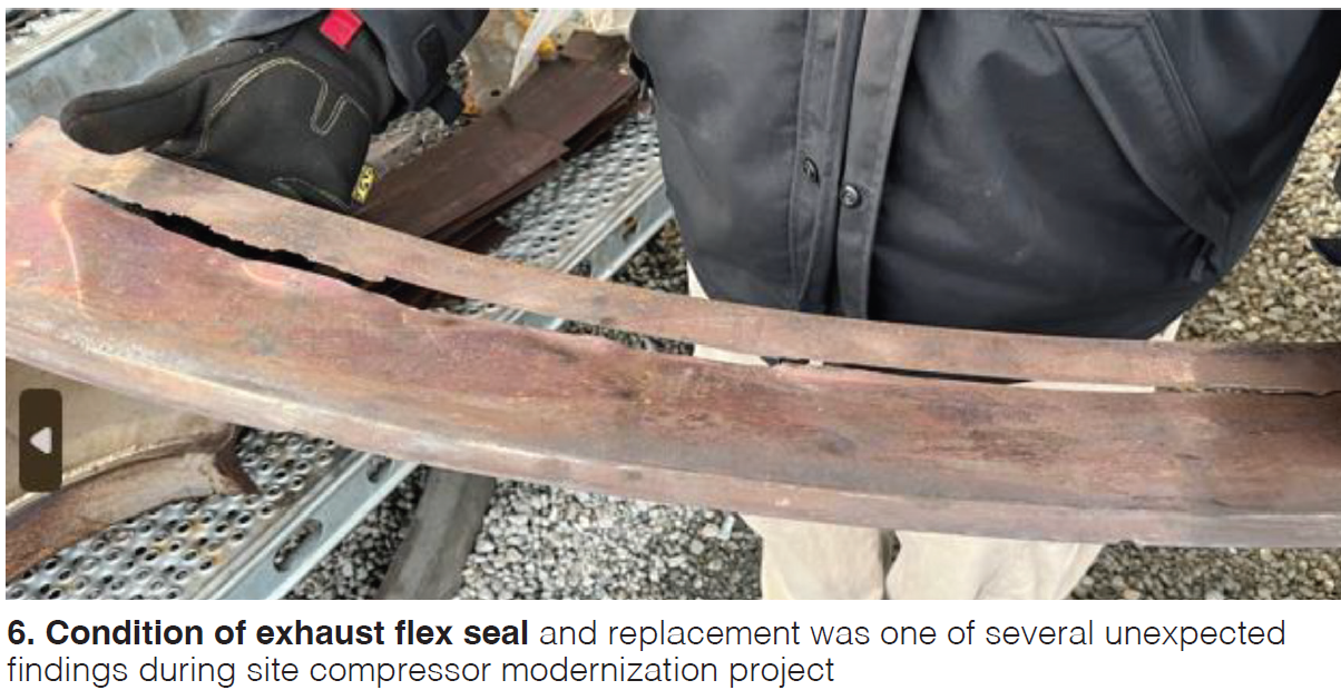
A 1994-vintage peaking facility in the southeast went through a compressor modernization, converting two 7FA.01 units to .03 (both unflared). For context, it’s a good idea to review the slides reviewing all the unit upgrades undertaken by this O/O over the last few years, especially the ones in question. This facility, like several others in the O/O fleet, were acquired from IPPs beginning in 2009.
However, the experiences and lessons learned are probably of most interest:
- Confirm properly sized and certified rotor lift beam
- Turbine casing bolt scrap rate of 90%
- Better coordination on turbine rotor dovetail cleaning prior to OEM TIL inspection
- Better oversight of OEM shop schedule and witnessing of shop work
- Better capital parts planning
- Unexpected modifications such as S1N inner support ring and thrust bearing
- Exhaust flex seal inspection and replacement (Fig 6)
- Auxiliary component refurbishments
- Value of third party oversight
- Need for a spare 7FH2 field for the fleet
Other major component replacements include the turning gear and the AO42 exhaust diffuser duct. The slide with the list of obsolescence/end of life concerns is also an eye-opener.
COMBUSTION SYSTEMS
Fire in the hole?
During a session on combustion, one user described the event which led to TIL2552 addressing fire protection trips. Several months after an HGP outage, one GT at a facility with two 3×1 CC blocks tripped on fire protection. CO2 had discharged into zone 1, combustor can 13 had “violently disassembled” at the end cap, and the turbine compartment door blew off its hinges, yet there was no active fire.
Damaged components (Fig. 7), such as the end caps and fuel nozzle assemblies for cans 12-14, fuel gas flex hose for can 13 (pig tails), and can 13 to 14 crossfire tube, were quickly replaced. Combustion and turbine sections went through BIs. Some cooling passages on the stage 1 nozzle were found to be clogged, requiring additional inspection work.
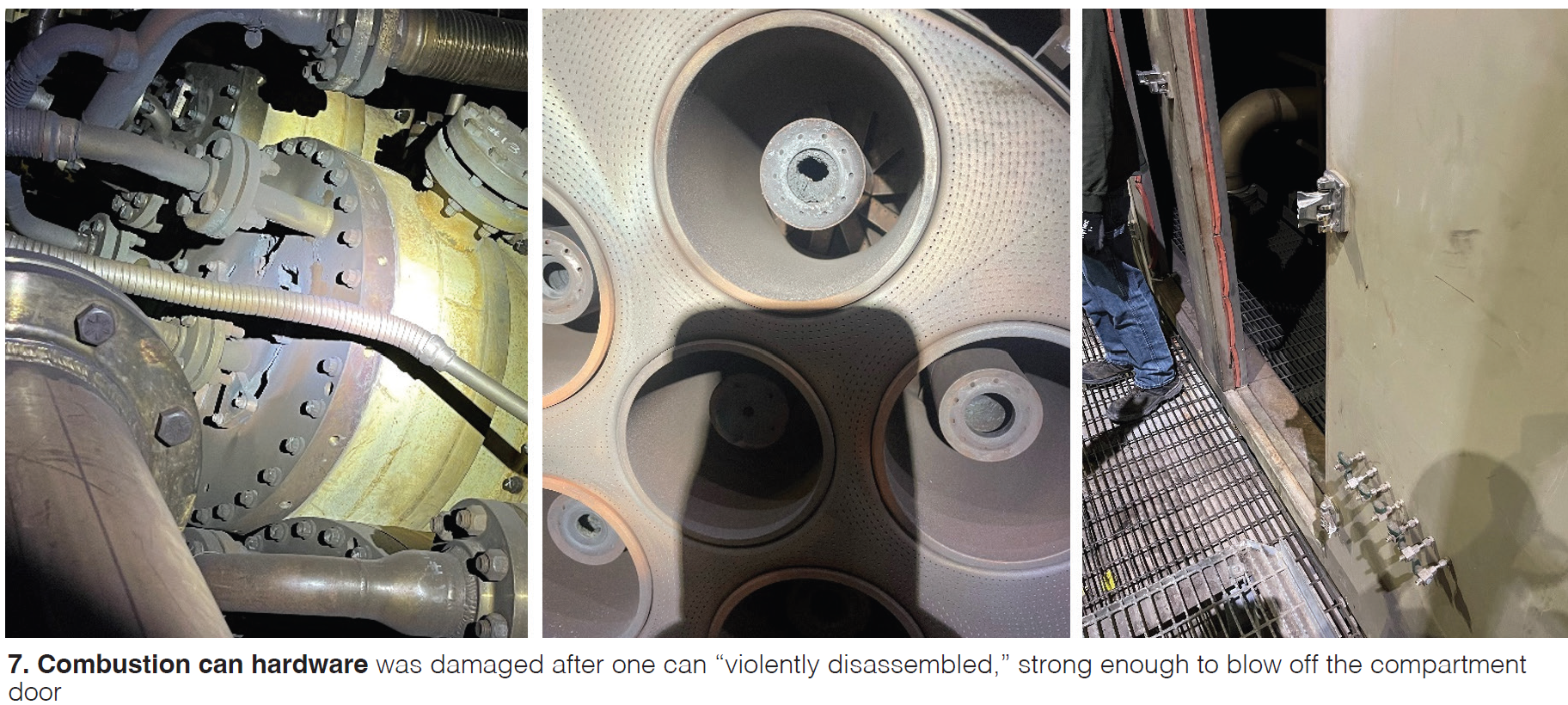
Why and why can 13? The RCA revealed that, after the outage, the site was dealing with a hot spot swirling back to can 13 or 14 for which tuning efforts were unsuccessful. Multiple subsequent BIs revealed nothing unusual. An engineering case was opened with the OEM and active at the time of the event. Other possible contributing factors were that the compartment was only rated for 2.5 in H20 pressure, the nozzles in can 13 may not have been refurbished or flow-tested, and the compartment door had surpassed its expected life of 20 years.
One year later, the OEM issued the TIL and stated that the unit exhibited elevated exhaust spreads, though remaining below trip limits. The O/O did not recognize this as a potential contributing factor during its initial investigation. Further, the O/O is concerned that the logic changes recommended in the TIL could result in even more trips.
One audience member reported his plant ran for 3-4 months after an HGP outage and also had combustion issues. At one point, bolts sheared off, liberating whole end caps. They don’t yet understand what caused the event.
Smoking a bad cigar. An undisclosed location experienced black smoke coming out of a liquid-fuel-fired (LF) unit, while the other two units on site were burning gas during a more frequent than projected dispatch schedule. Operators tuned the machine, checking the temperature spreads and pressure for every can. Cans 8 and 10 had their “candlesticks” replaced recently but they “looked like all the others,” so they were not tuned. One year earlier, the same cans exhibited low pressure but no smoke.
Questions posed to the audience were: Do we pre-emptively take a scheduled outage, record pressures when we operate/test on LF, and how frequently should we tune on LF?
One audience member noted that they were looking into adding pressure transmitters to 14 lines to identify when they are coking; another confirmed that they had done this and it “proved to be valuable.” It can be done for about $1000/PT using a wireless network to bring the data to the control room. A third suggested that not enough cooling air was being supplied during gas operation, which is affecting LF operation. Check the manifold, he advised. A fourth suggested check and, if necessary, repair all brazed joints on gas and LF fuel nozzles, adding that the OEM no longer makes brazed fuel nozzles.
CONTROLS
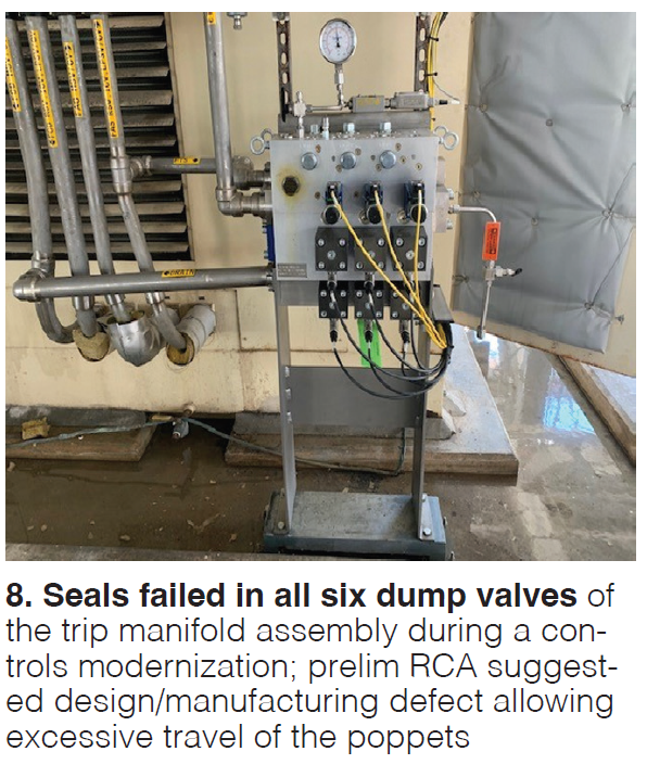
To a “triple major” outage last year, one site added a control system modernization and a complete cooling tower replacement. Scope on the controls included Mark VI to Mark VIe upgrade, migration of steam turbine/generator controls from Ovation to the Mark VIe, and an upgraded vibration monitoring package from System One to Orbit 60.
Overall performance results were impressive: 6.4% gain in net output, 2.1% heat rate improvement, 142-MW improvement in net 2×1 mode turndown, and 71-MW improvement in 1×1 mode turndown.
Challenges, observations, and lessons learned include:
- Failure of a capacitor in a digital valve positioner after 3000 hours service.
- Shortcomings in the valve hydraulics original design
- Seal failures in all six dump valves (Fig. 8) in the trip manifold assembly attributed to excessive travel of the valve poppets within their sleeves).
- Incompatabilities between the old and new ST/G trip controls logic design philosophy
- High turnover of OEM technical advisors and varied familiarity with systems
- Incorrect sizing of the HP main level valve
- Some TILs did not get captured in the upgrade
- 10-12 days required to commission control system per unit.
- Improvements necessary for lube oil lift valve hydraulic system and bleed capability.
- Long lead times required for GT electric components, such as fan motors and circ motor rebuilds
One audience cautioned that users should ask about Orbit 60 now if they are buying a new unit and another remarked that when they ordered an Orbit 60, the OEM showed up with the old 3500 system. A third said that the Orbit 60 rack is smaller than the 3500 but still fits into the original space.
GENERATORS
Bearing temperature creep
To address a persistent issue with 7FH2 B generator elliptical bearing temperature creep after every start (an issue that has been “talked about for years”), site replaced them with tilt pad bearings from a different OEM. One feature noted: The collector end has G-11 glass reinforced epoxy resin pads on the outer diameter for insulation. Replacement involved repositioning of the seismic and proximity probes, adding oil sight gages, and installing new lift oil tubing, fittings, flex hoses and attachment plate.
The slides include long-term temperature data from another user with three units which had been running with these bearings for a couple of years. Temperatures have been consistently running below 200F.
Many audience members had comments. One noted they had a third party rebuild the bearing in the shop. Eight or so users experience similar elevated temperatures and swap the bearings out regularly. One mentioned high bearing Ts on three units, and investigated the problem over eleven days with no solution. Finally, one notes similar experience with one bearing, “rolled it out” annually for several years, then did a realignment of the rotor and the problem went away. Apparently, TIL1611 addresses this issue and recommends changing the alignment to lower the rotor slightly.
A general discussion on generators revealed: six to seven audience members report replacing fields over the next five years, finding scaffolding that go 60 ft in the air and holds 40 tons is an “engineering challenge,” spare field and bars may not fit because of subtle nuances depending on what shop the bars originate from, inexperienced crews are being sent by the OEM (one asked for the manual), the wrong tooling was sent out on at least one occasion, and the TIL on the H2 seals calls for finer filters but this could lead to electrostatic issues.
BALANCE OF PLANT
Engineers from one of the largest CC facilities in the world (outside US) described the relocation of an H2 vent line to solve the problem of hydrogen drifting into the GT compartment via the ventilation blower. Site was experiencing persistently elevated haz gas readings from the detectors in the compartment, though there were no shutdown events caused by haz gas alarm.
Two possible entry points were suspected and evaluated, one from a damaged expansion joint in the ductwork and the other at the blower inlet. The latter proved to be the culprit.
While TIL1598 (from 2007) addresses vent pipe height, the solution here was to move the discharge point around ten feet away from the inlet filter house while retaining original height. The mod was performed on two of the GTs at the site and no subsequent high haz gas readings have been observed in two years. Note that the work requires purging of the generator.
Small mods, huge benefits
An industrial site O/O described relatively minor BOP modifications made to a 1998-vintage FA.02 (upgraded to a .03 in 2013) to “solve problems that they didn’t want to see again.” According to the presenter, “Our site gets a two-day shutdown each year and that’s it!”
Mods include:
- Decreased inlet fuel gas temperature from 130F to 97F.
- Upgraded compressor bleed valves – replaced OEM-supplied limit switches with more robust proximity sensors, replaced valve actuators with larger ones made of stainless steel and which use instrument air instead of compressor air.
- Modified exhaust pressure transmitter tubing with T fitting and 3-4 ft drain legs, added the lines to the operator rounds to check regularly for proper drainage.
- Replaced water-cooled flame scanners with dry-cooled versions from Reuter Stokes.
- Replaced exhaust pressure switches with Rosemount transmitters and relocated them to the roof.
Decreasing fuel gas temperature, the “biggest bang for the buck,” avoids adverse combustion dynamics during cold weather ops. Replacing compressor air with instrument air avoids condensate issues when sending hot fluid into a cold line. Allowing the condensate to collect in drain legs avoids incorrect pressure readings and pressure pulsations. With respect to the water-cooled flame detectors, it was difficult to remove air from spiral wound tubing. “Water near the turbine is always bad news,” said the presenter, “we worked with the vendor to improve the robustness of the design.” CCJ