


By David Clarida, Integrity Power Solutions LLC
You don’t have to visit many generating facilities powered by gas turbines (GTs) or attend many user-group meetings to realize that exhaust systems get little or no respect. These relatively simple systems essentially consist of metal components and insulation arranged to direct nominal 1000F gas exiting an engine to a heat-recovery steam generator (HRSG), or stack, while protecting personnel.
Exhaust systems usually are ignored on rounds, rarely getting more than a passing glance unless an operator hears gas whistling out of a hole, crack, or tear in the ductwork, expansion joint, or between mating faces of adjacent flanges. What’s there to check, anyway?
However, exhaust systems are not something to forget when an outage approaches. There are inspections you should make before and during an outage to evaluate the condition of system components. While most issues identified can be corrected at least temporarily with weld material and insulation, the wear and tear on these systems—particularly those at plants in cycling service—is considerable and their lifetimes are limited. Consider yourself lucky to get 15 years out of an exhaust system.
Purpose of this article is threefold: Help you assess the condition of your plant’s exhaust system, catch up on the latest designs which can help eliminate many of your recurring repair jobs, and gain from one plant’s experience in replacing the exhaust systems on its GTs.
A good exhaust system is defined here as one that can be used on any OEM’s gas turbine and has a quality insulating system. Equipment interfaces and site and owner requirements may impact the physical design, but most important is the thermal design, which depends on the insulating system.
Arrangement of the insulating system has evolved over time. Today’s offerings are much improved over those available only a few years ago, assuring users of longer operating lifetimes and a higher degree of personnel safety.
Exhaust systems are comprised of several components and vary depending on the turbine OEM. To illustrate: Frame engines manufactured by GE Energy for simple-cycle service typically are arranged as illustrated in Fig 1. Hot gas exits the GT via the exhaust frame and is distributed in the plenum by the diffuser. Exhaust then flows to the stack via ductwork, which is connected to the plenum and any associated ductwork by an expansion joint.
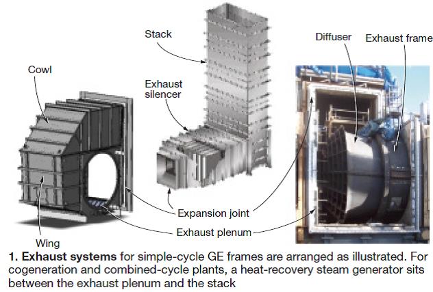
Focus here is on exhaust systems for GE frames 5, 6, and 7, which are similar in design.For GE frames serving in cogeneration and combined-cycle systems, the expansion joint at the back end of the plenum connects to the transition piece for the HRSG. GTs made by Siemens Energy are characterized by an exhaust cylinder bolted to the outlet flange of the engine. A so-called exhaust manifold bolts to the cylinder on one end and to the round (GT exit configuration)-to-square (HRSG inlet configuration) transition on the other. An expansion joint is located just upstream of the HRSG’s transition piece.
For GE machines, the exhaust frame is a structural part of the turbine and supports the aft bearing. It is in direct contact with turbine exhaust and not protected by insulation like the downstream exhaust plenum and ductwork. Years of demanding duty, frequent cycles, and/or overheating contribute to degradation conducive to early failures and costly forced outages.
Overheating also is known to cause turbine bearing issues, high lube-oil temperatures and resultant varnishing, and instrumentation failures. Important to maintaining your exhaust system in the condition required to achieve safety and dispatch goals are periodic inspections and follow-up repairs or replacement of components as necessary.
Knowing where to survey for damage and what type of wear and tear to look for are critical to success. Sidebars provide checklists for inspection of ductwork, frames, and diffusers. While the guidelines provided are specific to GE frames, they apply, in general, to exhaust systems offered by all frame OEMs.
Over the last several years, design of the frame and diffuser for 90-deg exhausts have improved significantly and these components are better able to accommodate the thermal stresses inherent in the original systems. Thus replacement of an exhaust frame and/or diffuser with one of upgraded design can both eliminate maintenance issues and significantly reduce the probability of premature failure.
Inspection of your system may suggest repairs or replacement of one or more exhaust-system components. Each situation is different and the decision to fix or replace must include a sound financial evaluation. In some instances, repairs have turned out more costly than a full replacement would have been. Annual repair costs add up and control of expenditures over the long term may suggest upgrade through full replacement earlier rather than later.
Design. Externally insulated exhaust duct systems still are in service on some legacy engines. For the purpose of personnel protection, this type of system may keep high temperatures from reaching the external cladding. However, the structural shell plant is prone to degradation and cracking because of direct exposure to exhaust temperature. Units that start daily usually are at greatest risk because thermal cycling accelerates the degradation process.
Inspection checklist for exhaust ductwork
Before outage
1. Take skin temperatures at several locations with a thermal imagery camera or a single-point temperature gun. Examples: flanges, areas where paint is burned, locations where excessive heat would pose a personnel hazard, etc. Skin temperatures above 250F-300F may indicate a problem with the insulation system. Temperatures above 650F are of particular concern because they can initiate degradation of the carbon steel shell and structure.
2. Listen for any internal noise. It can indicate a failure in the internal insulation system.
3. Inspect all expansion joints for uniform compression during operation. Look for burning or holes in the fabric belt or for holes in a metal-bellows expansion joint. Non-uniform compression can indicate improper thermally induced movement of exhaust ductwork.
4. Check turbine and load compartment temperatures. Are you able to enter compartments and get close to ductwork? Verify correct temperature ratings for vibration monitors in the load tunnel, which can run between 300F and 400F at base load for GE frames.
5. Verify lube-oil temperature is within manufacturer’s recommended range. High temperature is conducive to varnishing, which should be avoided.
During outage
6. Inspect the liners or insulation pans inside the exhaust plenum and ductwork. Verify that the insulation is in good condition and has not moved, creating “open” areas. Make repairs/add insulation as necessary.
7. Walk through the exhaust plenum and ductwork during the daylight hours, looking for holes/cracks in the shell plate and/or gaps between flanges.
8. Check for cracks in the external shell, structural members, and welds.
9. Check for wear marks on parts expected to move because of thermal expansion/contraction during heat-up and cool-down—including internal liner, duct-structure interfaces, etc—to verify that components are moving as designed.
10. Verify instrumentation (exhaust thermocouples, vibration detectors, etc) is in working order.
Internal insulation of exhaust ducts improves reliability and longevity by preventing direct exposure of the structural shell to exhaust gas temperatures. The challenge presented by this type of system is designing the insulation barrier to maintain its integrity and effectiveness during both base-load and cycling operation.
An internal “floating” liner design meets these requirements. Use of insulation pans (steel plans filled with insulation) does not provide the same level of protection and may actually allow direct exposure of the shell plate to the hot gases.
The floating-liner design consists of metal sheets that are secured, but not fastened, atop insulation compressed to an optimum density between the liner plates and the outer shell plate. Thus the liner is free to expand and contract throughout the various stages of operation.
The compressed insulation used today can withstand very high temperatures and is tight-fitting to minimize the potential for open spots where the hot gas can contact the outer walls of the ductwork. This is a great improvement over the mineral wool formerly used, which would break down and lose its insulating quality over time because of heat and turbulence.
Liner sheets are installed with a “scaled” effect that allows any liquids present within the exhaust to exit via a drain. This reduces the potential for water damage to the insulation and “slumping” of the material, which can cause the insulation to rot and gases to leak by and damage the shell.
In sum, modern exhaust systems are characterized by internally insulated ductwork, which minimizes stresses from high thermal gradients. The external gas-tight casing plate is maintained at temperatures only slightly above ambient, virtually eliminating problems caused by thermal expansion/contraction. The floating liner eliminates stresses inside the ductwork.
Case history: Optim Energy Altura Cogen
Altura Cogen’s staff, headed by Plant Manager Randy Cormier, relishes the challenges of major plant improvement projects. You feel the confidence as key personnel explain what they are doing and why. It seems as if no one ever “sits” at this facility: as one major project ends, the next one begins.
One reason is that Altura—formerly known as CoGen Lyondell—is an ageing and vital, must-run facility. The nominal 600-MW plant, owned by a subsidiary of Optim Energy LLC, is a 7E-powered 6 × 1 cogeneration facility which provides steam to a petrochemical complex and electricity both to that plant and the grid.
Readers may recall Altura Cogen’s recent success in reducing NOx emissions by more than 80%. This mega project included conversion of five 1985-vintage 7Es from diffusion-flame combustion systems to PSM’s (Jupiter, Fla) LEC III, installation of an inlet bleed heat system on each engine, and replacement of the original Mark IV GT control systems with Ovation® (Emerson Process Management’s Power & Water Solutions division, Pittsburgh).
Inspection checklist for frames, diffusers
Before outage
1. Check turbine and load compartment temperatures. Are you able to enter compartments and get close to ductwork? Verify correct temperature ratings for vibration monitors in the load tunnel, which can run between 300F and 400F at base load for GE frames.
2. Verify lube-oil temperature is within manufacturer’s recommended range. High temperature is conducive to varnishing, which should be avoided.
3. Inspect the frame assembly to see if the latest design is installed.
During outage
4. Inspect exhaust-frame flex and “L” seals for cracking and/or leakage. Telltale clue generally is high compartment temperature. Maintain a historical record of these data. Increasing temperature over time typically indicates leakage rate is increasing.
5. Check exhaust-frame strut airfoils for cracking and leakage.
6. Inspect diffuser turning vanes and struts for cracks.
7. Check the diffuser for circumferential cracking.
8. Inspect exhaust frame for flange deformation.
9. Verify instrumentation (exhaust thermocouples, vibration detectors, etc) is in working order.
Exhaust system retrofit. An upgrade project that had been on the minds of plant personnel for years was replacement of the 7E exhaust systems. Wear and tear of the so-called Generation 1 systems had reached the point where repairs were no longer practical or economic. Experts generally think an exhaust system should last upwards of about 15 years; these were well beyond that period of time.
Altura’s GT exhaust systems were characterized by (1) load-compartment temperatures that were too high to permit personnel access, (2) very high skin temperatures, and (3) the need for frequent replacement of expansion joints. Damage to the fabric joints was attributed to non-uniform expansion caused by a plenum so hot it didn’t expand the way designers had intended.
With today’s tight capital and O&M budgets, no plant manager wants to spend more than absolutely necessary to fix the problem at hand. In Altura’s case, this meant replacing the exhaust plenum, exhaust wing, and cowl, and the expansion joint connecting the plenum to the HRSG. The replacement third-generation exhaust system was provided by Integrity Power Solutions LLC with installation by Integrated Service Co LLC. Both companies are based in the Tulsa area and have personnel with expertise in inlet and exhaust system repair and replacement.
The components installed by InServ under the direction of Project Manager Gary Martin took less than four months to fabricate and deliver to the site; replacement of exhaust frames and diffusers would have added at least a couple of months to project start.
Plus, the optimal time for change-out of the exhaust frame typically is during a major inspection when the turbine is realigned. Recall that the GT’s aft bearing resides in the exhaust frame.
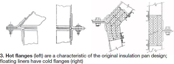
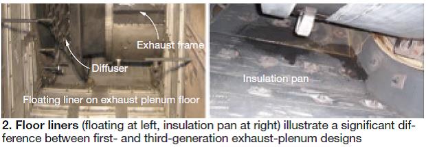
One of the issues with the original pan design was so-called “hot flanges” (Fig 3, left). Explanation: Thermal growth of a pan’s exposed surfaces does not match that of the outer perimeter, thereby causing distortion along that perimeter. Gaps occur between pans, allowing hot exhaust to contact the outer shell; distortion and cracking result.Two major benefits the third-generation exhaust system has over the original are (1) floating floor liners described earlier and (2) cold flanges. Fig 2 shows the floating liner for the exhaust plenum floor at the left; photo at right is of a first-generation insulation pan in the same location.
Floating liners have “cold flanges” (Fig 3, right), which are characterized by field-installed wrapped insulation pillows and liner plates. This design creates a continuously sealed thermal insulation barrier conducive to a cooler interface.
Result of the upgrade was a dramatic reduction in the external temperature of exhaust system components. “Even before the thermography survey was performed on the first unit upgraded,” Project Manager Daryl Whitfield said, “it was evident that its plenum was much cooler than those for the other machines.”
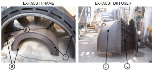
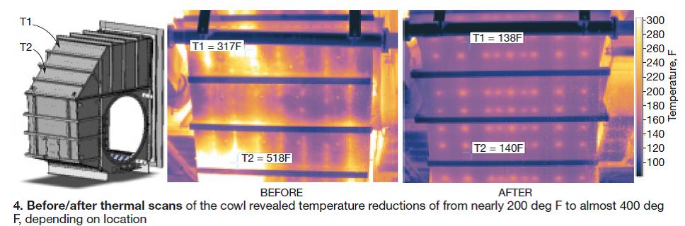
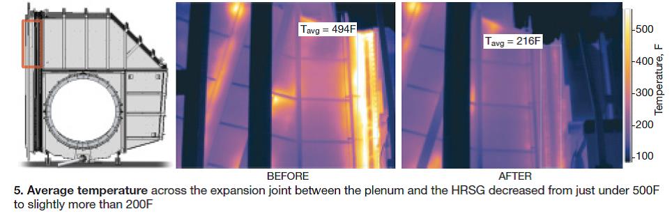
A thermographic survey showed just how much cooler the new third-generation exhaust system was compared to the original. For example, before/after thermal scans of the cowl revealed temperature reductions of from nearly 200 deg F to almost 400 deg F, depending on measurement location (Fig 4). Average temperature of the expansion joint between the plenum and the HRSG decreased from just under 500F to slightly more than 200F (Fig 5).
Whitfield was pleased. “The end product we received,” he said, “performed as expected and was a value when compared to our other options.” Cormier was cautiously optimistic, as you might expect of a seasoned plant manager. “As of now we are pleased with the performance of the new plenum,” he offered. “We expect this design to perform well and look forward to a positive evaluation over the plant’s lifetime.”
Allow for adequate cooling of the exhaust system—one to two days after removing the gas turbine from service. Do final parts inventory and other soft tasks during this time. Be sure to acquire all new bolts/hardware and flex seals. These should be included in the field kit supplied by the plenum manufacturer.How the job was done. Plenum replacement is not difficult if you take the time to properly plan and execute the project, and use experienced resources (Fig 6). Here’s a summary of the procedure used at Altura Cogen:
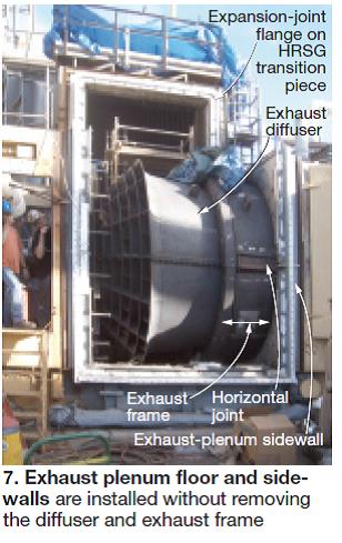
- Unbolt the wing and cowl from the plenum. Then unbolt the upper walls and cut out the lower half of the plenum. Important to note is that the diffuser and exhaust frame need not be removed to change-out the plenum.
- Cut the expansion joint connecting the plenum to the HRSG. Note that the expansion joint is bolted to the plenum side and welded on the other side to a flange on the HRSG. Next step typically is to clean, dress, and true-up the boiler flange. This can be time-consuming and challenging because metal moves and distorts over the years.
- Clean up the interfaces with the gas turbine as well.
- Install the new expansion joint and then the lower half of the plenum. Next, put the upper walls of the plenum in place and true-up the work before installing flex seals. Progress to this point is shown in Fig 7.
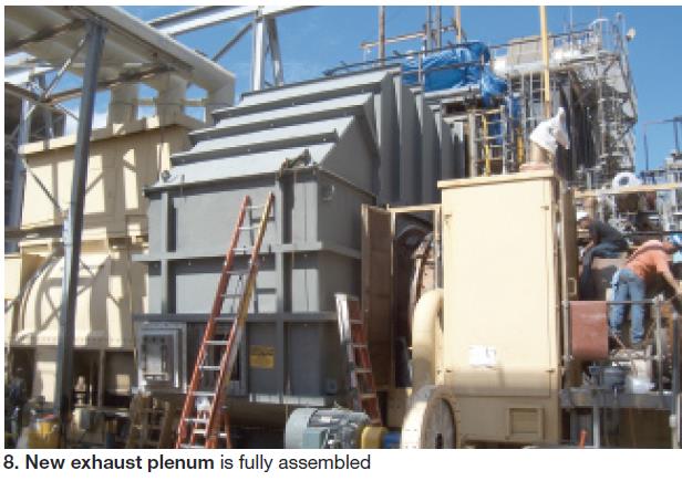
- Next the wing and cowl are replaced (Fig 8).
- Finally, insulation and liner are installed internal to the plenum at the joints. And the floating liner is bolted into the HRSG liner system.
David Clarida is president of Integrity Power Solutions LLC (david.clarida@ipsok.com), a full-service provider of GT inlet and exhaust system repairs and replacements. Before founding IPS, he was CHROEM™ product-line leader at GE Energy Services and aftermarket sales manager at Braden Manufacturing LLC. Clarida began his career as a project engineer for Western Farmers Electric Co-op.
The entire project was completed over 12 one-shift days. This means it’s possible to replace an exhaust plenum assembly for a Frame 7 engine during an extended combustion inspection, as well as during hot-gas-path and major inspections. ccj