LEGACY CONTROLS FORUM, NO. 5 IN A SERIES
By Luke Williams, PE, consultant
www.geLegacyGasTurbineSupport.com
Editor’s note. This article is based on material presented by the author in his training courses on gas- and steam-turbine controls to explain the reason for the algorithm described and how it works. Email clukewilliams@mindspring.com and ask to be notified of his upcoming controls training courses for GE aero and frame gas turbines.
With the introduction of the Mark IV digital control system, the calculation and display of thermocouple (t/c) input signals is done entirely by the processor—including cold-junction/short-circuit compensation, conversion of the millivolt signal to temperature, and open circuit biasing.
There was a perceived need to be able to “adjust” the temperature signal for hardware inaccuracies. The “adjustment” feature would be hidden to avoid confusion with the TTKX temperature control constants. A control constant, TTKXCOEF, was added to the temperature algorithm, scaled as a decimal. The range was 0.000 to 1.000.
Calibration verification of thermocouples in 1981 indicated that approximately half had quality problems, including failure to meet accuracy specifications. Further investigation determined that for a group of 25 new t/cs, the average reading was 5 deg F above calibration, ranging from 2 to 19-deg-F delta. The initial TTKXCOEF constant was set at 0.995, 5 deg F, or 1094.5 deg F at 1100F.
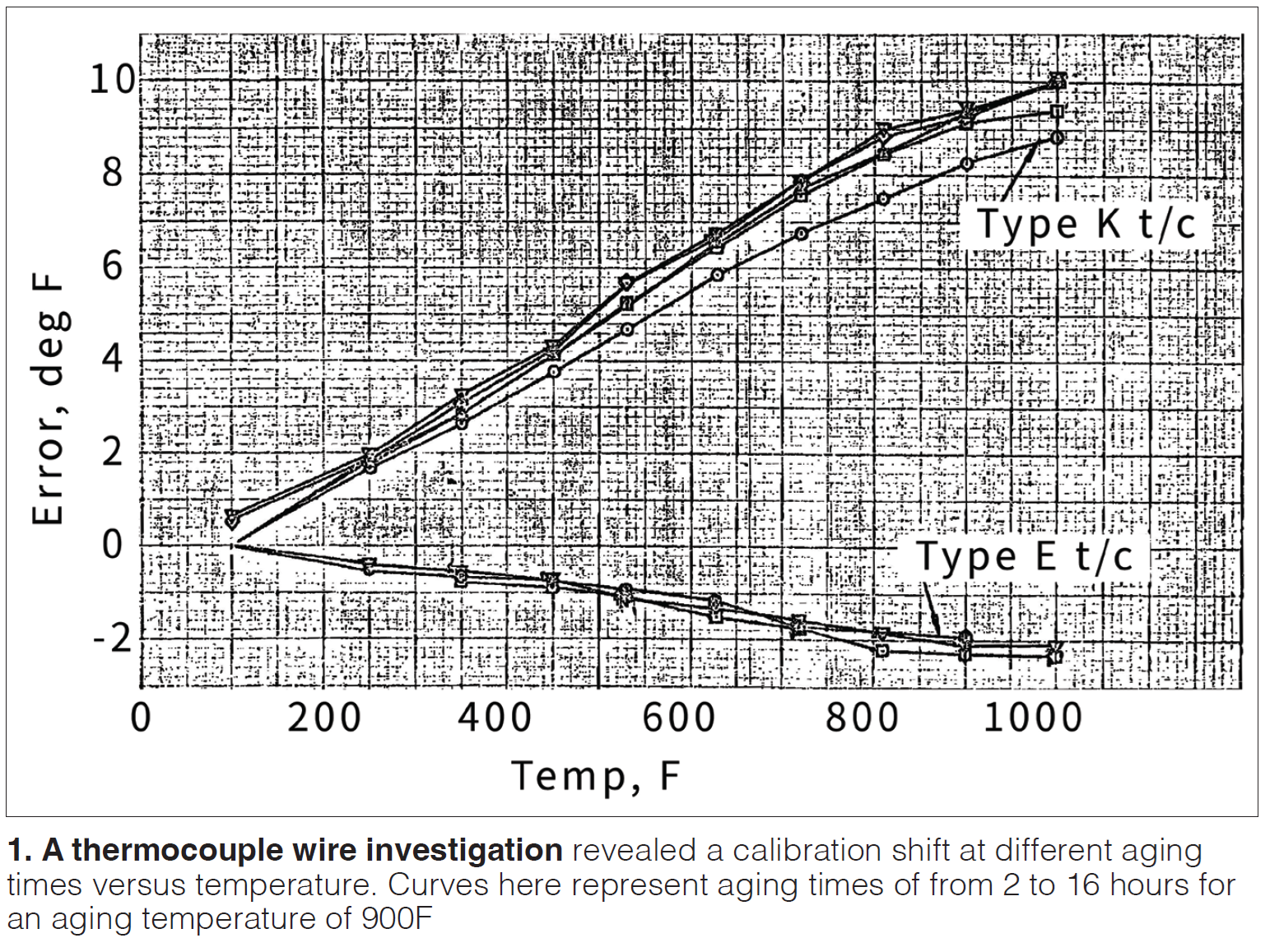
A GE Evendale (Ohio) report issued in 1977 noted that when Type K thermocouples were used in the 900F–1000F range their calibration shifted to indicate a higher temperature than actually existed. The phenomenon is metallurgical in nature. Conclusion: The thermocouple “ages” with temperature cycles, and the calibration shifts (Fig 1).
During the MS6001A “SPOTS” test in 1978, the exhaust thermocouples were indicating temperatures about 11 deg F higher than test-installed precision thermocouples. At that time, standard Type K t/cs (CrAl) were used with an expected accuracy of +8.25 deg F at 1100F. The same difference between standard and precision thermocouples was confirmed by several field-tested units.
In 1984, work was started on the MS7001EA 7A4 generator—a cost-reduced and uprated 7A6 design. Word on the street was that the cost reduction had some problems with the structural properties of the end covers and bearing supports. The 7A6 generator was rated 81.5 MW. It was also rumored that the output of the 7A6 generator did not meet performance expectations. More rumors suggested that the generator losses were underestimated. Generator losses are on the order of 1 to 1.5 kW.
In 1988, a “paper uprate” of from 81.5 to 83.3 MW (a 1.7% increase) was proposed for the 7001EA. The justification for the uprate was statistical data that indicated the average inlet pressure drop on field units was 2.5 in. H2O instead of the 4.0 in. H2O included in the performance guarantee at that time. A second justification was the introduction of the bias constant TTKXCOEF in Mark IV. However, no change to the value of the constant was recommended.
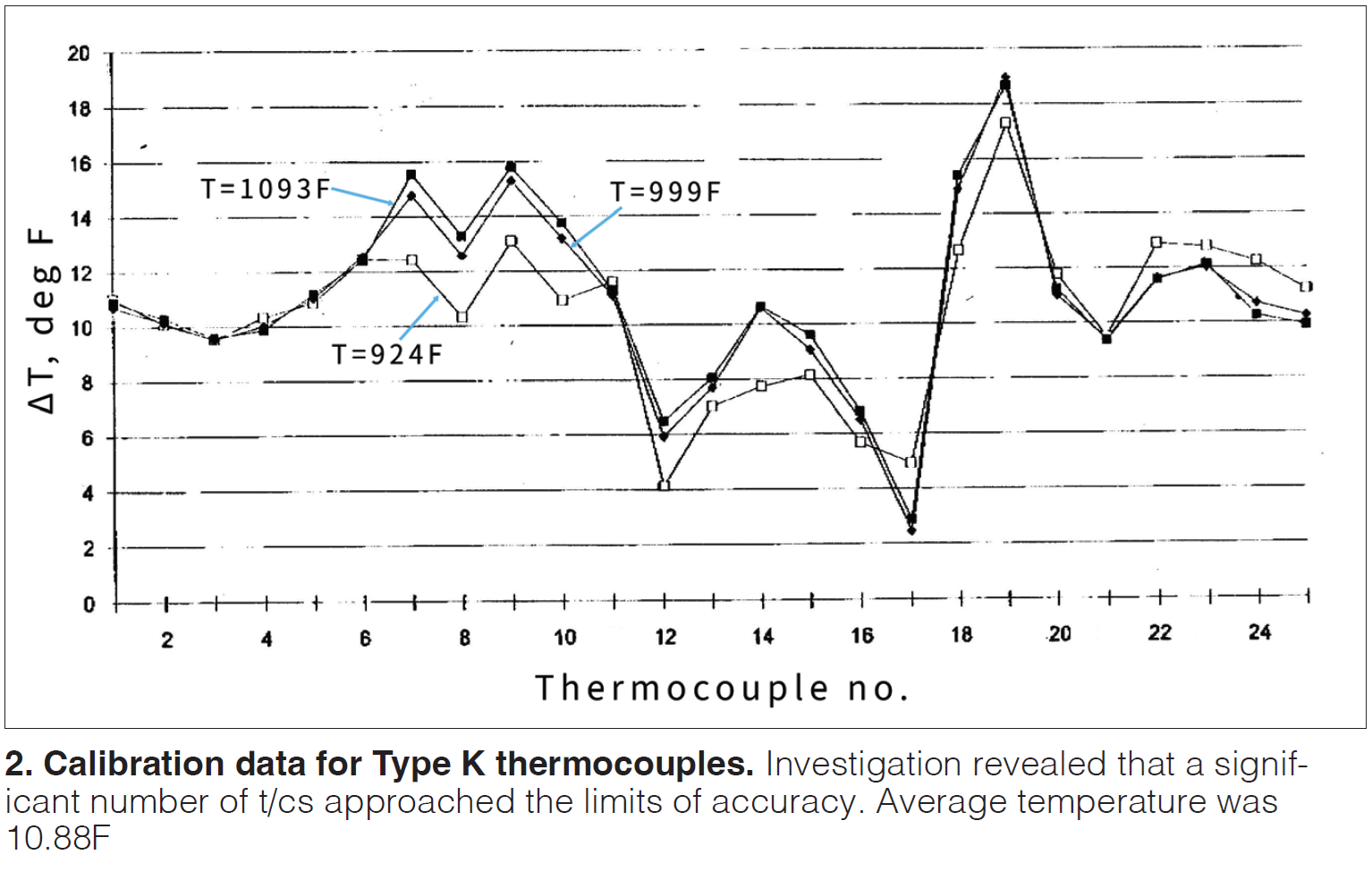
In 1993, a Performance Task Force (PTF) was formed to investigate the actual accuracy of thermocouples received. Result: A significant number of t/cs were found to approach the limits of accuracy (Fig 2).
A result of the PTF’s findings was that the value of the constant TTKXCOEF was revised from 0.995 to 0.989. This corresponded to a calibration difference of 12.1 deg F. The conclusion was to use only precision Type K (CrAl) thermocouples with an expected accuracy of +4.4 deg F at 1100F.
The performance shortfall rumored after introduction of the 7A6 generator seemed to have been resolved.
After 1995, all turbines shipped were outfitted with precision Type K thermocouples. The OEM issued Technical Information Letters (TILs) recommending the replacement of standard Type K t/cs with precision Type K instrumentation. Vendor quality was improved by assuring dimensional and material consistency of the wire material and heat treating after swaging. A set of 25 t/cs were tested at elevated temperatures to assess the results of improvements (Fig 3).
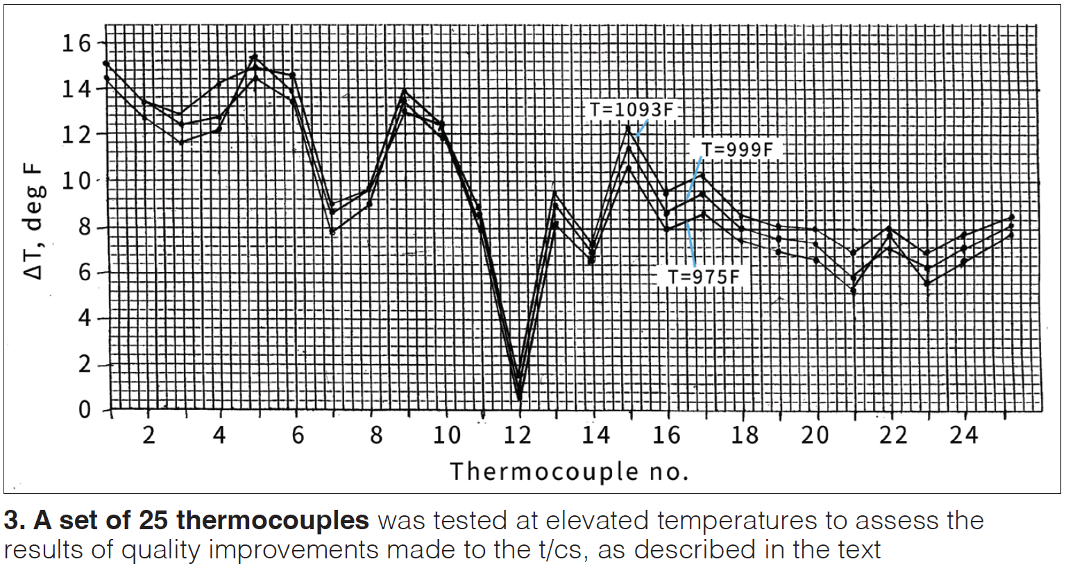
The out-of-limits reading for t/c 12 indicates a defective sample. The average error to the calibration temperature was 10.0 deg F. The expected error of precision t/cs is +4 deg F. With the exception of No. 12, all thermocouples were within the expected accuracy.
Reports over time from the field indicated that some of the MS7001EAs had the TTKXCOEF constant set at a lower value than the 0.989 introduced in 1993. For every 10-deg-F increase in exhaust temperature control, an increase of 1.0% in output would result.
The TTKXCOEF constant in the Mark IV is behind a secondary password. To access this display, select “MENU 20 Enter.” The CRT should go blank. Select MENU button “F5 Enter.” Insert the secondary password “12673.” The screen should display the TTKXCOEF constant and the system frequency selection.
In Mark V, the constant is listed in the CONST_Q.SRC file where it can be accessed by anyone.
Mark VI has three constants: TTKXCOEF, TTKXCOEF Part Load, and TTKXCOEF Base Load. All are accessible to the user.
Introduction of the constant apparently was discussed at a customer conference and resulted in several customers assuming that their units had some sort of performance shortfall. They saw the coefficient as a convenient way to increase output. However, as noted above, decreasing the constant results in overfiring and more rapid degradation of parts.
Using the constant to bias the exhaust temperature has drawbacks. First, it ignores the characteristics of the thermocouples actually installed. The 0.989 constant was based on a sample of 25 t/cs by averaging the actual-to-recorded temperature differences. The difference ranged from a low of 0.54 deg F to a high of 18.90 deg F.
What if all 18 t/cs installed on MS5001P, 5002B, 6001A and B, and 3002J tended to the low difference? The 12-deg-F exhaust bias would result in overfiring the unit by 22 deg F, or 20% of the peak rating. Note that 20% of peak rating results in a reduction in maintenance interval of 3200 hours.
The question of thermocouple accuracy and benefit of correcting for that accuracy is debatable considering the basic thermocouple accuracy of +4.4 deg F and the effect of overfiring by 7.3 deg F.
The thermocouple correction coefficient TTKXCOEF should be set to 1.0 for all units and applications.
Finally, the t/c correction coefficient TTKXCOEF could be used to correct a demonstrated thermocouple accuracy problem if all 18 t/cs were calibrated at base temperatures and demonstrated a consistent error. CCJ