The International Association for the Properties of Water and Steam (IAPWS) opened its Power Cycle Chemistry (PCC) webinar series, with Dr. Barry Dooley presenting and David Addison moderating, outlining how repeat cycle chemistry situations (RCCS) drive the majority of chemistry-influenced failures in fossil and combined-cycle/HRSG fleets. The message was direct: failures are patterned, measurable, and preventable when plants adopt current IAPWS Technical Guidance Documents (TGDs) instead of allowing RCCS to continue.
RCCS in the field
RCCS are recurring gaps in monitoring, controls, and procedures. Typical examples include unknown or excessive corrosion-product transport, high HP evaporator deposits, carryover above action levels, insufficient on-line instrumentation and/or reliance on grab samples, outdated treatment philosophies and guidelines, and lack of shutdown protection. Evidence of failures/damage indicates that plants operating with two or more RCCS are far more likely to suffer tube failures, FAC, and/or PTZ steam turbine damage.
High-risk mechanisms
Under-deposit corrosion (hydrogen damage). When corrosion products accumulate in HRSG HP evaporators, contaminants (often chloride) concentrate beneath deposits and initiate hydrogen damage, producing brittle tube failures. Control requires measuring total feedwater iron, trending HP evaporator deposition, and scheduling cleaning before “reaction products” appear at the deposit base. The IAPWS Technical Guidance Documents TGD6-13 (Corrosion Products) and TGD7-16 (Internal Deposits) address all aspects of these corrosion mechanisms and thus prevent failure.
Flow-accelerated corrosion (FAC). Still the leading HRSG failure mechanism and a safety issue in fossil feedwater lines. It is necessary to differentiate single-phase from two-phase FAC as they are controlled by different cycle chemistries. Apply AVT(O) or OT for single-phase locations, raise pH25 (to ~9.6–9.8 as needed) for two-phase zones, and verify that the levels of total iron are in agreement with the IAPWS achievable guidance values (TGD6-13 (Corrosion Products)). Avoid reducing agents in HRSG service.
Steam-turbine PTZ pitting, SCC, and corrosion-fatigue. Failures initiate at pits formed during moist layups, not because of steady-state steam purity. Protect LP turbine sections with dehumidified air (DHA) applied before ~72 hours of shutdown. Instrument for steam purity, measure drum carryover, and avoid attemperation during contamination events. The IAPWS Guidance addresses all aspects of these corrosion mechanisms and thus prevent failure (TGD5-13 (Steam Purity) and TGD1-08 (Carryover)).
New tools
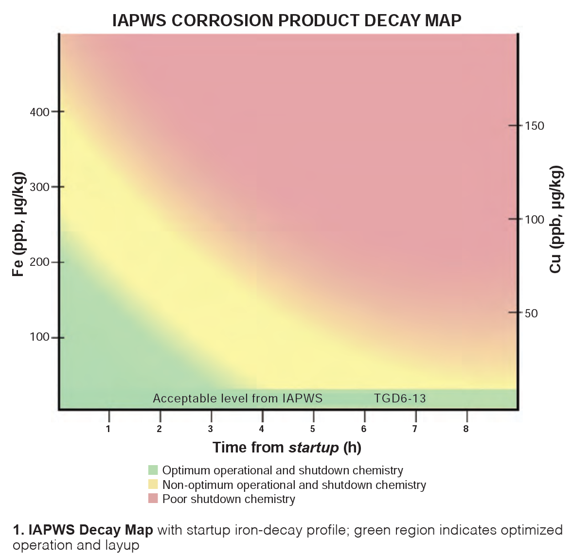
IAPWS Decay Map for startups. For fast-start/frequently started units, plot the startup iron-decay profile (using a proxy technique such as turbidity correlated to total Fe) and overlay the profile on the IAPWS Decay Map. Profiles in the “Green” area of the decay map indicate optimized operation and layup; profiles in the “red/yellow” area indicate high iron transport into boilers and possible elevated internal deposit levels which can initiate UDC (under-deposit corrosion). The white paper details procedures and use cases including ACC fleets and FFS verification.
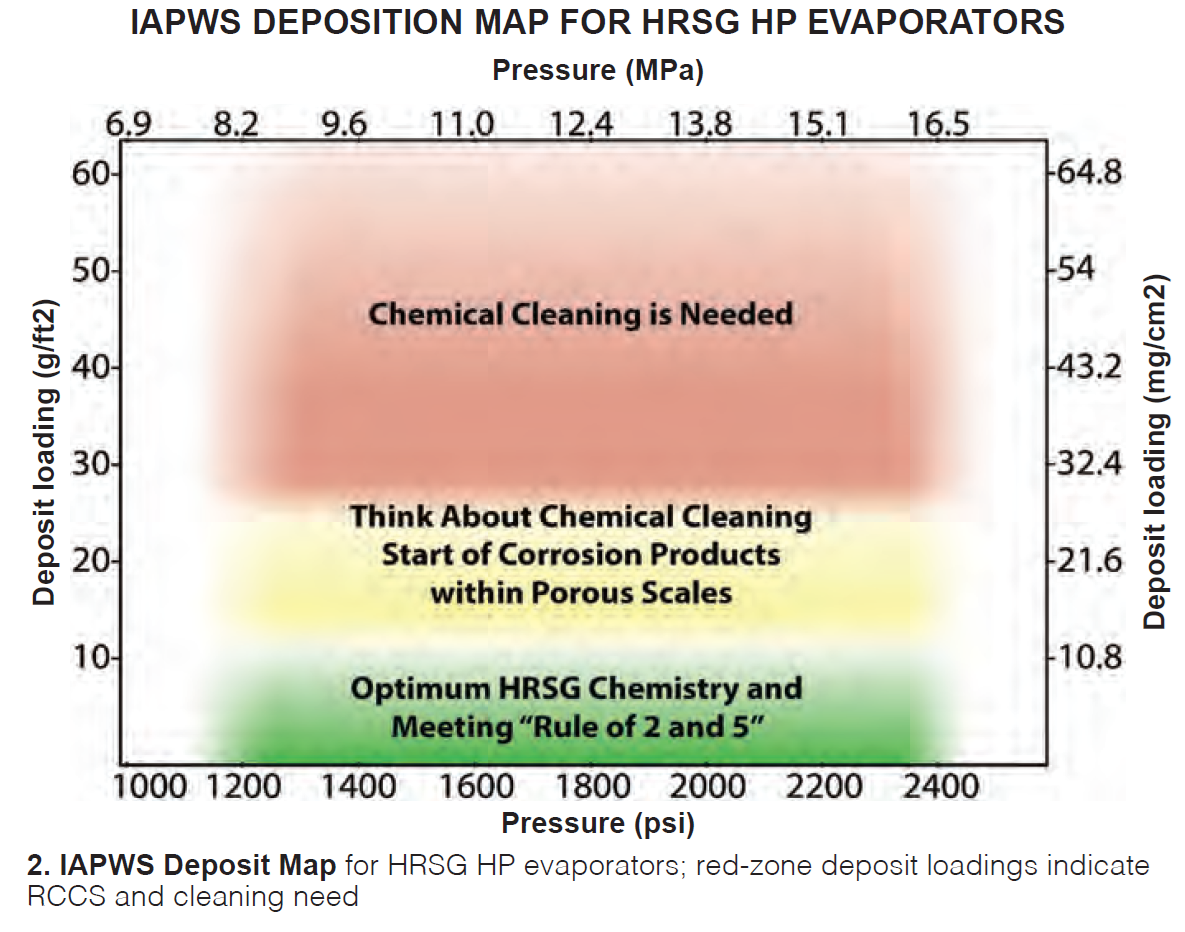
IAPWS Deposit Map for HP evaporators. Remove lead-tube samples (initially within the first ~20,000 operating hours) and place measured deposit loading on the map to determine cleaning need. Red-zone results indicate an RCCS and elevated UDC risk. A strong warning for use of a film-forming substance (FFS) indicated that an FFS should not be applied with heavy deposits in the red area of the deposit map. The IAPWS FFS Guidance (TGD11-19) suggests that deposits are characterized before application of an FFS (Section 8 review).
Immediate actions
- Download and implement the relevant freely available IAPWS documents at www.iapws.org: Corrosion Products, HRSG HP Evaporator Deposits, Steam Purity, Instrumentation, Volatile Treatments, PT/CT, Carryover, FFS and the January 2025 white paper on startup iron decay.
- Trend total Fe and use the Decay Map to tune startup and layup; improvements are when the profiles move into the green area with procedure and chemistry changes.
- Inspect deposits with the IAPWS Deposit Map, schedule cleaning on evidence, and verify results with post-clean Fe trending.
- Close instrumentation gaps (alarm-enabled, online) and set action/shutdown levels aligned to IAPWS guidance.
- Eliminate reducing agents in HRSG service; raise pH for two-phase FAC zones; stop attemperation during contamination.
- Standardize DHA for LP turbine sections; treat shutdowns as critical chemistry events.
Nuggets to remember
With IAPWS PCC Chair Addison and Dooley, the large global virtual audience drove a candid, robust information exchange. Highlights follow:
- HP evaporator sampling for internal deposits. First sample within ~20,000 hours; lead tube near outlet on horizontal-gas-path HRSGs. Interval thereafter depends on findings.
- Iron measurement. Always digest samples; spectrophotometer without digestion measures only a small fraction of total Fe. Millipore Filters don’t provide sufficient accuracy. Establish proxy correlation (turbidity ↔ Fe) and Decay Map.
- OT oxygen levels. No strict “upper limit” is required in once-through service; for all units a focus on achieving very low total Fe at economizer inlet is needed. Watch cation conductivity.
- IP drum pH anomalies. Verify calibration, chemical identity, dose point, and mixing. Instrument issues and incorrect line-ups are common causes.
- FAC control. Don’t rely on oxygen addition to solve two-phase FAC; increase pH and verify by iron trending. Identify the FAC type by surface morphology before addressing any chemistry changes.
- FFS use. Perform a Section 8 deposit review first (this is in FFS guidance document); avoid adding FFS to heavily deposited HP evaporators.
- LP turbine layup. Apply DHA before ~3 days of downtime; shutdown chemistry matters as much as operating chemistry.
Final word
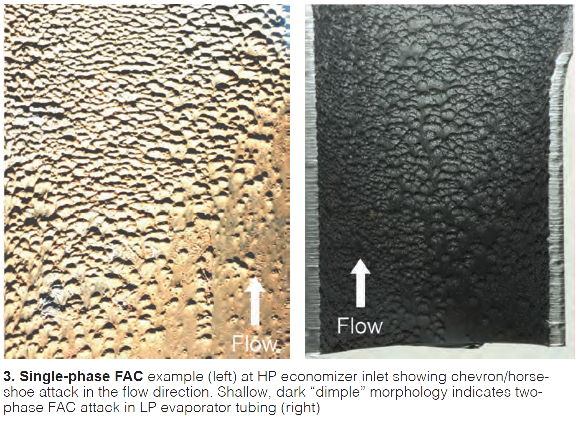
View the webinar recording above to see example Decay Map overlays, deposit/reaction-product micrographs, and FAC morphology side-by-side (Fig 3), useful visuals when educating station leadership and maintenance teams.
RCCS are measurable, repeatable, and correctable. Plants that adopt the TGDs, instrument to alarmed standards, verify with iron-decay and deposit maps, and protect turbines during shutdowns cut forced-outage risk while stabilizing heat-rate and component life. The discipline is the work. All the IAPWS guidance documents referenced are freely available at www.iapws.org. CCJ